Control method, system, electronic device and storage medium of single-phase off-grid inverter
A control method and inverter technology, applied in collectors, electric energy management, electric vehicles, etc., can solve problems such as complex AC load characteristics, difficulty in suppressing periodic voltage distortion, and inverter output voltage distortion, and achieve the elimination of inverter To solve the problem of output voltage distortion, improve adaptability, and improve the effect of dynamic response
- Summary
- Abstract
- Description
- Claims
- Application Information
AI Technical Summary
Problems solved by technology
Method used
Image
Examples
Embodiment 1
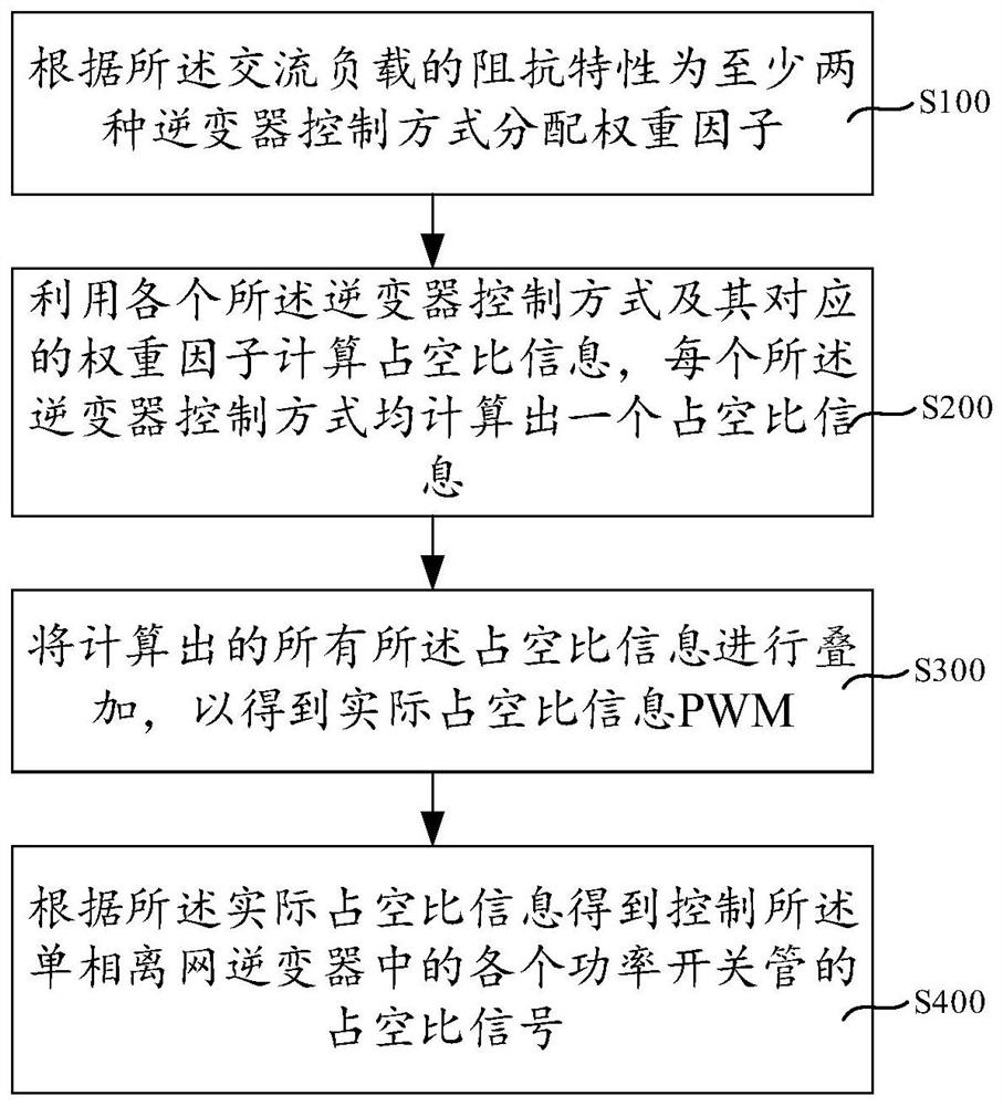
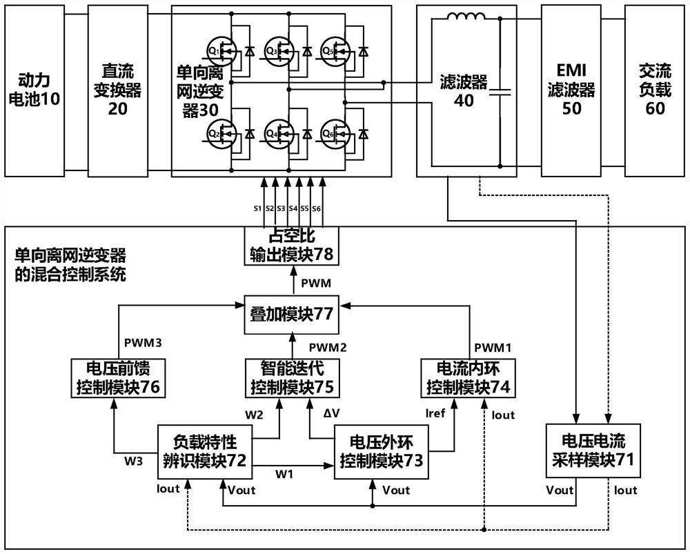
[0098] figure 1 The flow chart of the hybrid control method of the single-phase off-grid inverter provided by the present invention, figure 2 It is a structural block diagram of the hybrid control system of the single-phase off-grid inverter provided by the present invention. like figure 1 and figure 2 As shown, this embodiment provides a hybrid control method and system for a single-phase off-grid inverter. It should be noted that the control method for a single-phase off-grid inverter in this embodiment can be applied to the A control system for a single-phase off-grid inverter, the control system for a single-phase off-grid inverter can be configured on an electronic device. The electronic device may be a personal computer, a mobile terminal, etc., and the mobile terminal may be a hardware device with various operating systems, such as a mobile phone and a tablet computer.
[0099] like figure 2As shown, the hybrid control system of the single-phase off-grid inverte...
Embodiment 2
[0160] Figure 8 It is a schematic diagram of the voltage outer loop control module 73 and the current inner loop control module 74 provided in this embodiment. combine figure 2 and Figure 8 , the difference from Embodiment 1 is that in this embodiment, the current reference limiting unit 734 may only use the first predetermined amplitude limit to limit the amplitude of the basic reference current signal Iref' to generate the reference current signal Iref. The second subtractor 741 makes a difference between the current sampling signal Iout and the reference current signal Iref to generate a current error signal ΔI, and the second R control unit 742 performs resonance adjustment on the current error signal ΔI to generate a current error signal ΔI. The first basic duty cycle information PWM1'. The first duty cycle limiting unit 743 may use the first weight factor W1 and the second predetermined amplitude limit value to perform amplitude limitation on the first duty cycle in...
Embodiment 3
[0162] Figure 9 This is a schematic diagram of the control system of the single-phase off-grid inverter provided in this embodiment. like Figure 9 As shown, the difference from Embodiment 1 and Embodiment 2 is that, in this embodiment, the voltage / current loop control mode is a voltage single-loop control mode. The inverter control module in the control system of the single-phase off-grid inverter includes a voltage single-loop control module 79 , an intelligent iterative control module 75 and a voltage feedforward control module 76 .
[0163] When the first duty cycle information PWM1 is calculated by using the voltage single-loop control method and the first weighting factor W1, the voltage error signal ΔV is obtained by making the difference between the voltage sampling signal Vout and the reference voltage signal Vref, Then perform R control on the voltage error signal ΔV to obtain the first basic duty cycle information PWM1', and then use the first weight factor W1 an...
PUM
 Abstract
Description
Claims
Application Information
 - R&D
- Intellectual Property
- Life Sciences
- Materials
- Tech Scout
- Unparalleled Data Quality
- Higher Quality Content
- 60% Fewer Hallucinations
Browse by: Latest US Patents, China's latest patents, Technical Efficacy Thesaurus, Application Domain, Technology Topic, Popular Technical Reports.
© 2025 PatSnap. All rights reserved.Legal|Privacy policy|Modern Slavery Act Transparency Statement|Sitemap|About US| Contact US: help@patsnap.com


