Eureka AIR delivers breakthrough ideas for toughest innovation challenges, trusted by R&D personnel around the world.

Automatic control production equipment with convenient feeding

A technology of production equipment and barrel, which is applied in the direction of solid separation, filter screen, grille, etc., can solve the problems of easy blockage of the device, easy rework, and reduced feeding efficiency, so as to avoid raw material residue, realize position transfer, and improve The effect of feeding efficiency

Active Publication Date: 2021-06-01
广州渺钛新材料科技有限公司
View PDF16 Cites 2 Cited by
  • Summary
  • Abstract
  • Description
  • Claims
  • Application Information

AI Technical Summary

Problems solved by technology

[0004] 1. The comparative document CN110562673A discloses a drying tower that is convenient for feeding, "comprising a drying tower body, and above the drying tower body, a feeding bin integrally formed with the drying tower body, an anti-clogging device, a feeding Conveying device, the anti-clogging device is detachably installed on the feed bin, the feeding and conveying device is arranged above the anti-clogging device, and the feeding and conveying device includes a frame, a conveyor belt, a driving wheel assembly, and a driven wheel assembly and the tensioning wheel assembly, the driving wheel assembly, the driven wheel assembly and the tensioning wheel assembly are all rotatably mounted on the frame, and the conveyor belt is sleeved on the driving wheel assembly, the driven wheel assembly and the tensioning wheel assembly; The invention provides a conveyor belt, which is driven by the power of the driving wheel assembly, under the support of the driven wheel assembly and the tension of the tension wheel assembly, and stably transports the materials that need to be dried on the frame. Realize automatic feeding, reduce labor intensity, and improve work efficiency", but the height of the barrel cannot be changed with the reduction of internal raw materials during the working process of the device, resulting in the height of the bottom of the feeding part inside the device being higher than the bottom of the barrel , there is a certain vertical distance between the raw material and the feeding part, and the feeding work cannot be continued, so the feeding is not complete and the feeding efficiency is reduced;
[0005] 2. The reference document CN110976005A discloses a biomass particle fuel pulverizing device with a pressing function, "comprising a pulverizing device, the pulverizing device includes a first pulverizing chamber and a second pulverizing chamber, and the bottom of the second pulverizing chamber is installed There is a pulverizing motor, the output shaft of the pulverizing motor is connected with the first rotating shaft through a coupling, and the outside of the first rotating shaft is correspondingly provided with a hammer plate frame, and the two hammer plate frames are respectively located in the first crushing chamber and the second Inside the crushing chamber, crushing parts are evenly arranged on the hammer plate frame, an intermediate screen is arranged between the first crushing chamber and the second crushing chamber, and a feeding port is opened on the top of the first crushing chamber. The crushing part is an L-shaped blade, the corner of the end of the L-shaped blade is an obtuse angle, and a rotating scraper is sleeved on the outside of the first rotating shaft, and the rotating scraper is located on the top of the middle screen. It is in the shape of a fan blade, and the present invention has the characteristics of avoiding material deposition and high work efficiency", but the device cannot achieve the corresponding purpose of grading and crushing, and rework is prone to occur, resulting in low crushing efficiency of the device;
The left end of the lower end of the crushing box is provided with a discharge port. There are two long crushing rollers opposite to each other. The two long crushing rollers rotate at the same speed in the crushing box and in opposite directions. Below the two long crushing rollers, a plurality of feeding holes I are evenly distributed on the long board I, the long board I is arranged on the upper end of the crushing box, and the left and right sides of the sprinkling box are provided with rectangular through holes, through which the long board I passes through. Through the two rectangular through holes on the sprinkler box, the sprinkler box is slidably connected to the long plate I, and the size of the multiple drop holes I can be adjusted, but the vibration screening cannot be realized inside the device, which makes the screening device inside the device easy Blockage occurs, reducing screening efficiency

Method used


Image

  • Automatic control production equipment with convenient feeding
  • Automatic control production equipment with convenient feeding
  • Automatic control production equipment with convenient feeding

Examples


Embodiment Construction

[0038] The following will clearly and completely describe the technical solutions in the embodiments of the present invention with reference to the accompanying drawings in the embodiments of the present invention. Obviously, the described embodiments are only some, not all, embodiments of the present invention. Based on the embodiments of the present invention, all other embodiments obtained by persons of ordinary skill in the art without making creative efforts belong to the protection scope of the present invention.

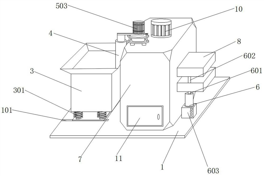
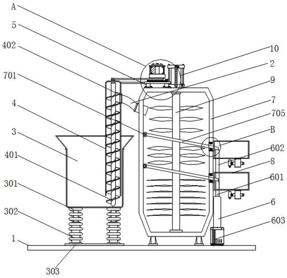
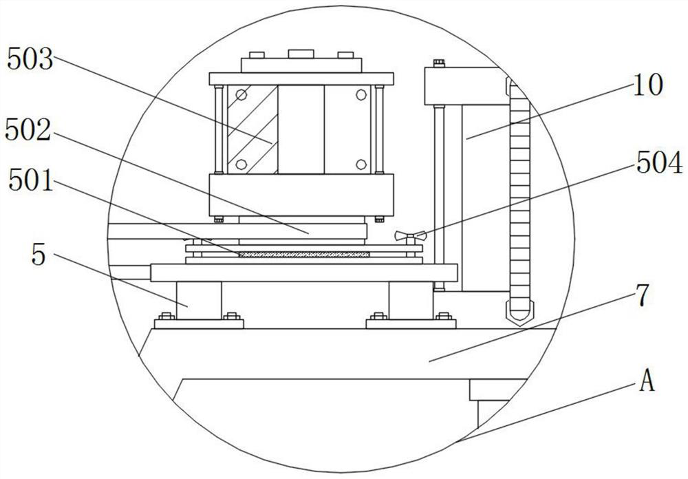
[0039] see Figure 1-Figure 10 , an embodiment provided by the present invention: an automatic control production equipment that is convenient for feeding, including a working base plate 1, a connecting pipe 2, a material cylinder 3, a feeding pipe 4, an electric telescopic rod 5, a telescopic sleeve 6 and a crushing cylinder 7. The top surface of the working base 1 is provided with a chute 101. The working base 1 can increase the overall contact area between ...


PUM


Abstract

The invention discloses automatic control production equipment with convenient feeding. The automatic control production equipment comprises a working bottom plate, a connecting pipe, a charging barrel, a feeding pipe, an electric telescopic rod, a telescopic sleeve and a crushing barrel, wherein the charging barrel is welded to the top of the telescopic rod, the bottom of the charging barrel is connected with the top of an extension spring, the smashing barrel is installed at the top of the working bottom plate through a supporting frame, a cutting rod is mounted in the crushing barrel through a bearing, a vibration motor is mounted at the top of the working bottom plate, and the telescopic sleeve is mounted at the output end of the vibration motor. By arranging the charging barrel, when the weight of raw materials in the charging barrel is reduced, the extrusion effect on the extension spring is weakened, then the extension spring drives the telescopic rod to move upwards under the reset effect, so as to drive the charging barrel to ascend, and therefore the raw materials at the bottom of the charging barrel can make contact with the bottom of a screw rod, and can also be fed into the crushing barrel, raw material residues are avoided, and the feeding efficiency of the device is improved.

Description

technical field [0001] The invention relates to the technical field of feeding production, in particular to an automatic control production equipment that is convenient for feeding. Background technique [0002] The existing automatic control production equipment replaces labor by machines, which improves the processing efficiency and reduces the labor burden of the staff, and the feeding is the premise to ensure that the production and processing equipment can process raw materials during work. Manual feeding and feeding are difficult to meet the raw material requirements of machine processing, so an automatic control production equipment that is convenient for feeding is needed to assist enterprises in corresponding production and processing operations. [0003] The defective that existing production equipment exists is: [0004] 1. The comparative document CN110562673A discloses a drying tower that is convenient for feeding, "comprising a drying tower body, and above the...

Claims


Application Information

Patent Timeline
Patent Type & Authority Applications(China)
IPC IPC(8): B02C18/10B02C18/18B02C18/24B02C18/22B02C23/14B02C23/16B07B1/28B07B1/42B07B1/46
CPCB02C18/10B02C18/18B02C18/24B02C18/2258B02C23/14B02C23/16B07B1/28B07B1/42B07B1/46B02C2023/165
Inventor 龙春梅
Owner 广州渺钛新材料科技有限公司
Why Eureka
Eureka Blog
Learn More