
Intelligent conveying system of particle pump and test run method of intelligent conveying system

A technology for intelligent conveying and particle pumps, applied in pump testing, parts of pumping devices for elastic fluids, pumps, etc., can solve problems such as increasing product costs, low intelligence level, and easy breakage

Pending Publication Date: 2021-06-01
宁波得利时泵业有限公司
View PDF0 Cites 0 Cited by
  • Summary
  • Abstract
  • Description
  • Claims
  • Application Information

AI Technical Summary

Problems solved by technology

However, fresh fruit particles are easily broken after being heated and sterilized. In addition, the existing technology generally uses centrifugal pumps, rotor pumps, etc. for transportation, and the rotor pump relies on the rotation of the rotor to make the fluid flow. A certain shear force is generated on the fruit particles in the fluid, which further intensifies the crushing of the fruit particles during the transportation process, resulting in a great waste of fruit resources and greatly increasing the product cost. Similarly, the centrifugal pump also has a large shear force
In addition, the intelligence level of existing particle pump conveying devices is also low

Method used


Image

  • Intelligent conveying system of particle pump and test run method of intelligent conveying system
  • Intelligent conveying system of particle pump and test run method of intelligent conveying system
  • Intelligent conveying system of particle pump and test run method of intelligent conveying system

Examples


Embodiment 1

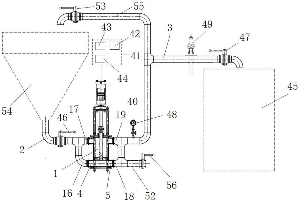
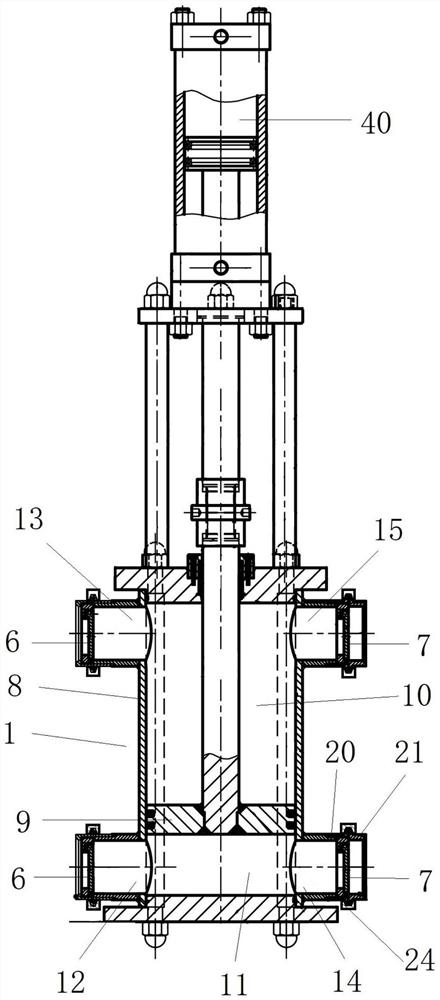
[0034]An intelligent conveying system of a particle pump, which includes a piston pump 1, a liquid inlet pipeline 2, a liquid outlet pipeline 3, a material receiving barrel 45, and a hydraulic system 41, and the piston pump 1 is provided with at least one liquid inlet 4 and at least one A liquid outlet 5, the liquid inlet pipe 2 communicates with the liquid inlet 4 of the piston pump 1, one end of the liquid outlet pipe 3 communicates with the liquid outlet 5 of the piston pump 1, and the other end extends into the connection On the barrel 45, the liquid inlet pipe 2 is provided with a first switch 46 for opening or closing the liquid inlet pipe 2, and the liquid outlet pipe 3 is provided with a pressure detection device 48, a throttle valve 49, and a Open or close the second switch 47 of the liquid outlet pipeline 3, the hydraulic system 41 includes a hydraulic cylinder 40 for driving the piston pump 1, and a hydraulic station for supplying oil to the hydraulic cylinder 40, an...

Embodiment 2

[0049] A test method for an intelligent conveying system of a particle pump is characterized in that it comprises the following steps:

[0050] (1) The clean water medium is used for the first test, the no-load test is carried out first, and then the throttle valve 49 is adjusted to carry out a multi-stage boost test;

[0051] (2) The follow-up test adopts the medium containing fruit particles, first carries out the no-load test, then adjusts the throttle valve 49, and carries out the multi-stage boost test; under each pressure section, all carry out the test of various viscosity medium, and pass After measuring and calculating the volumetric efficiency value of the material volume of the receiving tank 45 within a certain period of time, it is judged whether the volumetric efficiency value is greater than the first set value, and if so, the viscosity of the corresponding medium under the corresponding pressure section and the frequency conversion corresponding to the volumetri...


PUM


Abstract

The invention provides an intelligent conveying system of a particle pump. The intelligent conveying system is characterized by comprising a piston pump, a liquid inlet pipeline, a liquid outlet pipeline, a material receiving barrel and a hydraulic system, wherein the piston pump is provided with at least one liquid inlet and at least one liquid outlet, the liquid inlet pipeline communicates with the liquid inlet of the piston pump, one end of the liquid outlet pipeline communicates with the liquid outlet of the piston pump, and the other end of the liquid outlet pipeline stretches into the material receiving barrel; a first switch is arranged on the liquid inlet pipeline, and a pressure detection device, a throttling valve and a second switch are arranged on the liquid outlet pipeline; and the hydraulic system comprises a hydraulic cylinder and a hydraulic station, the hydraulic station comprises a PLC, a variable frequency motor and a hydraulic pump, the PLC is electrically connected with the variable frequency motor, the variable frequency motor is electrically connected with the hydraulic pump, the hydraulic pump is connected with the hydraulic cylinder, and the hydraulic cylinder is connected with the piston pump. By means of the intelligent conveying system of the particle pump, materials can be effectively protected and conveyed without damage, and the intelligent level is high. The invention further provides a test run method of the intelligent conveying system of the particle pump.

Description

technical field [0001] The invention relates to the technical field of pumps, in particular to an intelligent conveying system of a particle pump and a test method thereof. Background technique [0002] At present, after processing and high-temperature sterilization, fresh fruit products need to be transported to the packaging workshop through pipelines for post-processing such as packaging. However, fresh fruit particles are easily broken after being heated and sterilized. In addition, the existing technology generally uses centrifugal pumps, rotor pumps, etc. for transportation, and the rotor pump relies on the rotation of the rotor to make the fluid flow. A certain shear force is generated on the fruit particles in the fluid, which further intensifies the crushing of the fruit particles during the transportation process, resulting in a great waste of fruit resources and greatly increasing the product cost. Similarly, the centrifugal pump also has a large shear force. In ...

Claims


Application Information

Patent Timeline
IPC IPC(8): F04B15/02F04B9/113F04B53/16F04B53/22F04B53/10F04B51/00
CPCF04B9/113F04B15/02F04B51/00F04B53/102F04B53/16F04B53/162F04B53/22
Inventor 聂如国
Owner 宁波得利时泵业有限公司
Learn More