Novel wood-burning particle furnace

A technology of burning wood and pellets, which is applied in the direction of combustion method, combustion equipment, fuel supply, etc. It can solve the problems of plate heat exchange heat loss, insufficient combustion, and blockage of the combustion bowl, so as to save operating costs, achieve good heating effect, and thermal efficiency high effect

Pending Publication Date: 2021-06-01
烟台炉旺节能科技有限公司
View PDF5 Cites 0 Cited by
  • Summary
  • Abstract
  • Description
  • Claims
  • Application Information

AI Technical Summary

Problems solved by technology

[0006] The present invention aims to solve the problem that the coking of wood-burning particles in the prior art will affect the exhaust air and block the combustion bowl, resulting in reduced air volume, insufficient combustion, and lack of oxygen, which will cause the furnace to stall, and the auger will jam. In severe case

Method used


Image

  • Novel wood-burning particle furnace
  • Novel wood-burning particle furnace
  • Novel wood-burning particle furnace

Examples


Embodiment 1

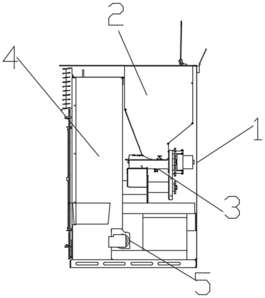
[0044] Such as figure 1 As shown, a new type of wood-burning pellet stove includes a shell 1, a feed port 2, a combustion system 3, a heat converter 4 and an exhaust device 5. The feed port 2 is arranged on the upper end of the shell 1, and the feed port 2 is connected to the combustion The input end of the system 3 and the output end of the combustion system 3 are connected to the input end of the heat converter 4 .

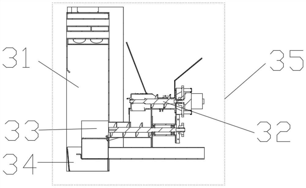
[0045] Such as figure 2 As shown, the combustion system 3 includes a combustion chamber 31, a conveyor 32, a combustion bowl 33, an ash tray 34, and a control system 35. The combustion chamber 31 is arranged on one side of the shell 1, and the input end of the conveyor 32 is connected to the outlet of the feed port 2. The output end of the conveyor 32 is arranged on one side of the combustion chamber 31 to connect with the combustion bowl 33, the combustion bowl 33 is arranged on the inner wall of the combustion chamber 31, the ash tray 34 is arranged directly...

Embodiment 2

[0056] Such as figure 1 As shown, a new type of wood-burning pellet stove includes a shell 1, an inlet 2 for putting fuel into the wood-burning pellet stove, and a combustion system 3 for charging and burning the fuel put into the inlet 2 , a heat exchanger 4 for transferring heat to the cold air in the housing 1 , and an exhaust device 5 for discharging the heated air out of the housing 1 .

[0057] Such as figure 2 As shown, the combustion system 3 includes a combustion chamber 31, a conveyor 32, a combustion bowl 33, an ash tray 34, and a control system 35. The combustion chamber 31 is arranged on one side of the shell 1, and the input end of the conveyor 32 is connected to the outlet of the feed port 2. The output end of the conveyor 32 is arranged on one side of the combustion chamber 31 to connect with the combustion bowl 33, the combustion bowl 33 is arranged on the inner wall of the combustion chamber 31, the ash tray 34 is arranged directly below the combustion bowl...


PUM


Abstract

The invention provides a novel wood-burning particle furnace. The furnace comprises a shell, a feeding port, a burning system, a heat converter and an exhaust device, wherein the feeding port is formed in the upper end of the shell and is connected with the input end of the burning system, and the output end of the burning system is connected with the input end of the heat converter; the burning system comprises a burning chamber, a conveyor, a burning bowl and an ash tray, the burning chamber is arranged on one side of the shell, the input end of the conveyor is connected with an outlet of the feeding port, the output end of the conveyor is arranged on one side of the burning chamber and is connected with the burning bowl, the burning bowl is arranged on the inner side wall of the burning chamber, and the ash tray is arranged under the burning bowl; and the heat converter comprises a heat transfer pipe set and an air duct, the heat transfer pipe set is horizontally arranged at the upper end in the burning chamber, the input end of the air duct is arranged above the heat transfer pipe set and communicates with the upper surface of the burning chamber, and a pipe body of the air duct is tightly attached to the inner side wall of the burning chamber.

Description

technical field [0001] The invention relates to the field of biomass stoves, in particular to a novel wood-burning pellet stove. Background technique [0002] Biomass boiler is a type of boiler, that is, boilers that use biomass energy as fuel are called biomass boilers, which are divided into biomass steam boilers, biomass hot water boilers, biomass heaters, biomass heat-conducting oil furnaces, Type biomass boilers, horizontal biomass boilers, etc. Among them, the biomass heater is a heater that burns biomass fuel to heat the air for heating. [0003] In view of the different quality of wood-burning pellets in the market, especially the coked pellets, the traditional stove blows out the ash powder by blowing air, which cannot meet the combustion requirements, because the pellets will affect the exhaust air after coking, block the combustion bowl, and reduce the air volume. , Insufficient combustion, lack of oxygen, resulting in the flameout of the furnace, auger material ...

Claims


Application Information

Patent Timeline
IPC IPC(8): F23B40/00F23K3/14F23J1/06
CPCF23B40/00F23K3/14F23J1/06
Inventor 辛京龙
Owner 烟台炉旺节能科技有限公司
Why Eureka
Try Eureka