
Two-phase flow state testing device of plate-fin heat exchanger and reconstruction method of two-phase flow state testing device

A plate-fin heat exchanger and flow state technology, applied in the field of optical detection, can solve the problems of great difficulty in obtaining information on phase distribution and flow characteristics of heat exchangers, and less research on boiling heat transfer characteristics, achieving reduction Complexity, the effect of improving real-time performance

Active Publication Date: 2021-06-01
HANGZHOU ZHONGTAI CRYOGENIC TECHNOLOGY CORPORATION
View PDF6 Cites 0 Cited by
  • Summary
  • Abstract
  • Description
  • Claims
  • Application Information

AI Technical Summary

Problems solved by technology

At present, the research on the heat transfer characteristics in the channel of the plate-fin heat exchanger and the optimization of the fin size mainly focus on the single-phase fluid convective heat transfer, while the research on the boiling heat transfer characteristics of the coolant in the heat exchanger has a phase change. There are few related studies
At the same time, because the plate-fin heat exchanger has a closed metal structure and complex vapor-liquid two-phase flow, it is extremely difficult to obtain information about the phase distribution and flow characteristics inside the heat exchanger.

Method used


Image

  • Two-phase flow state testing device of plate-fin heat exchanger and reconstruction method of two-phase flow state testing device
  • Two-phase flow state testing device of plate-fin heat exchanger and reconstruction method of two-phase flow state testing device
  • Two-phase flow state testing device of plate-fin heat exchanger and reconstruction method of two-phase flow state testing device

Examples


Embodiment Construction

[0048] The present invention will be further elaborated and illustrated below in conjunction with the accompanying drawings and specific embodiments. The technical features of the various implementations in the present invention can be combined accordingly on the premise that there is no conflict with each other.

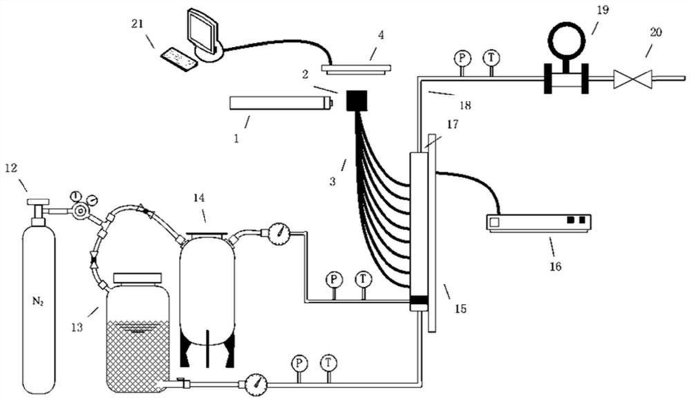
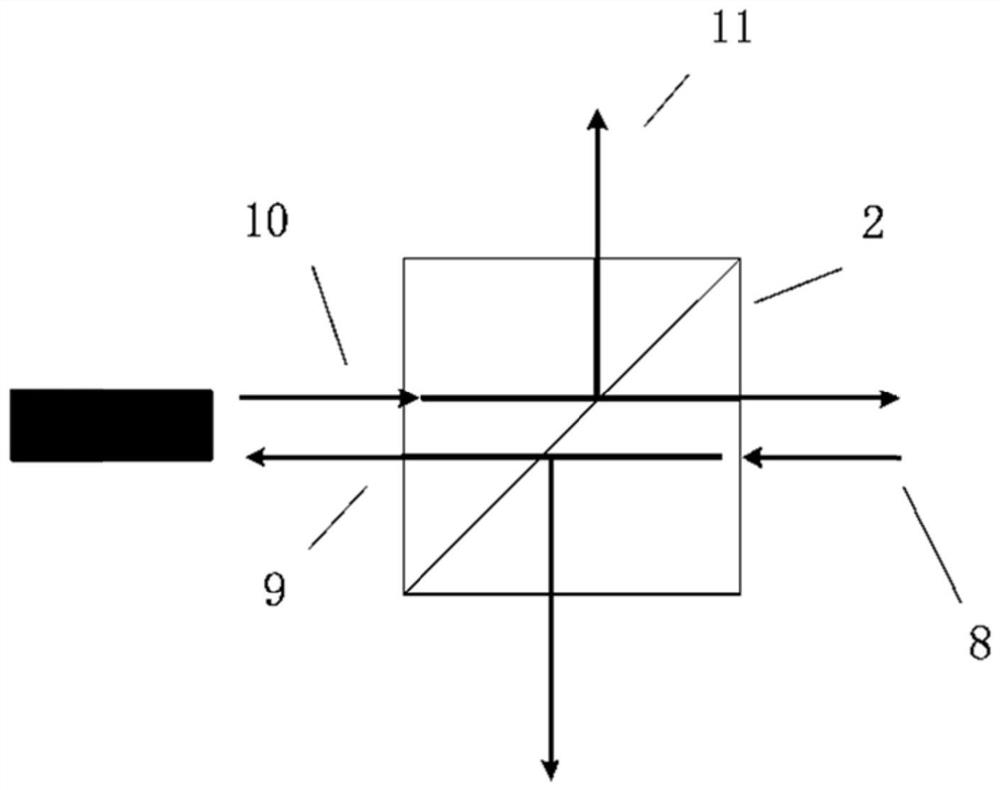
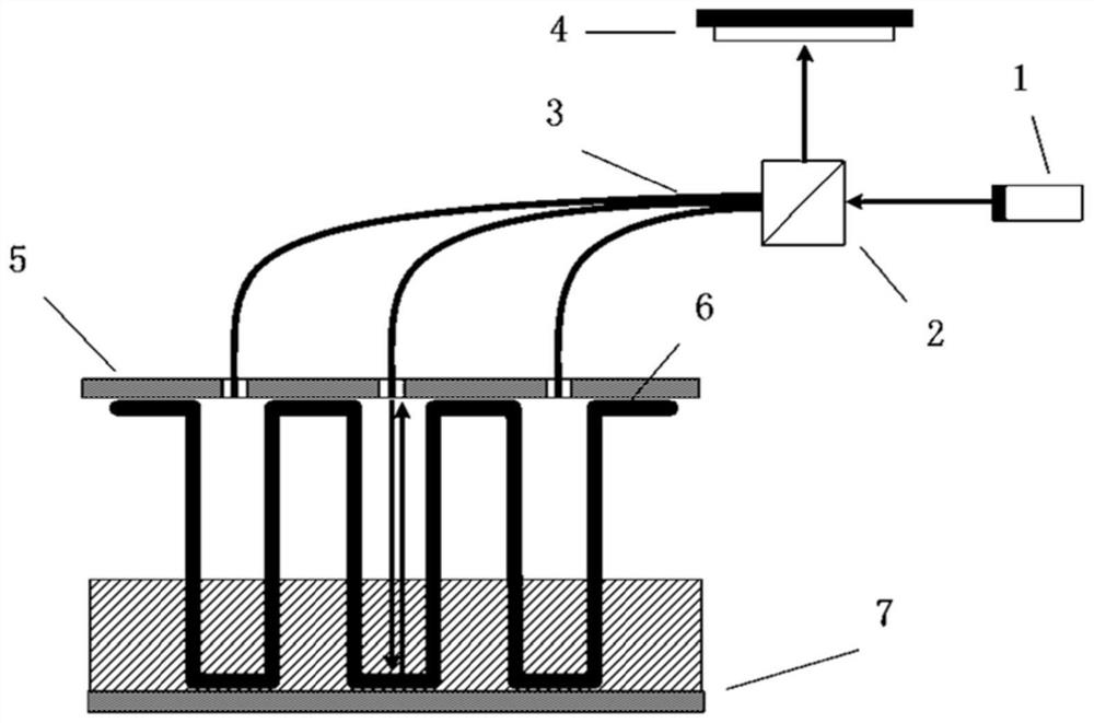
[0049] Such as figure 1As shown, the present invention provides a two-phase flow state testing device of a plate-fin heat exchanger, the two-phase flow state testing device includes a constant temperature liquid tank 13, a constant temperature gas tank 14, a plate-fin heat exchanger 17, a spectroscopic mirror 2, laser 1, photodetector 4 and processing module 21.

[0050] The liquid inlet of the plate-fin heat exchanger 17 is communicated with the constant temperature liquid tank 13 through the liquid inlet pipeline, and the liquid phase medium is passed into the plate-fin heat exchanger 17 by the constant temperature liquid tank 13. The air inlet of the plate-fin ...


PUM


Abstract

The invention discloses a two-phase flow state testing device of a plate-fin heat exchanger and a reconstruction method of the two-phase flow state testing device. A liquid inlet and an air inlet of the plate-fin heat exchanger in the device are respectively communicated with a constant-temperature liquid tank and a constant-temperature air tank; a lower partition plate of the plate-fin heat exchanger is externally connected with a heating device; a plurality of through matrix type detection ports are uniformly formed in an upper partition plate; an optical fiber bundle is arranged in each detection port; one ends of the optical fiber bundles are sealed and fixed in the detection ports; the other ends of the optical fiber bundles are connected with the emitting end of a spectroscope; the other side, opposite to the emitting end, of the spectroscope is an incident end; a laser device is perpendicular to the incident end and is arranged at an interval; a photoelectric detector for receiving a detection signal is arranged at the receiving end at an interval; and the photoelectric detector is externally connected with a processing module. According to the two-phase flow state testing device of the plate-fin heat exchanger and the reconstruction method of the two-phase flow state testing device provided by the invention, sampling through holes are evenly formed in the specific position of the upper partition plate, and the laser signals capable of reflecting the internal two-phase state are obtained through the multi-core optical fiber bundles, so that the vapor-liquid phase distribution condition in the whole range of the plate-fin heat exchanger is obtained.

Description

technical field [0001] The invention belongs to the technical field of optical detection, and relates to a two-phase flow state testing device of a plate-fin heat exchanger and a reconstruction method thereof. Background technique [0002] Plate-fin heat exchanger is a kind of heat exchange equipment with compact structure, light weight and high heat transfer efficiency. It has high specific surface area, large number of heat transfer units, and high-efficiency heat transfer characteristics. It is suitable for occasions with complex flow channel layout. It is widely used in industrial sectors such as petrochemical, aviation, vehicles, power machinery, air separation, cryogenic fields, atomic energy and aerospace, and has made remarkable achievements in utilizing heat energy, recovering waste heat, saving raw materials, reducing costs and some special purposes. economic benefits. [0003] In recent years, with the rapid development of industry, the demand for efficient trans...

Claims


Application Information

Patent Timeline
Patent Type & Authority Applications(China)
IPC IPC(8): F28D9/00G01M99/00
CPCF28D9/00G01M99/002
Inventor 章有虎张国兴
Owner HANGZHOU ZHONGTAI CRYOGENIC TECHNOLOGY CORPORATION
Learn More