
Unmanned aerial vehicle control system based on portable electro-oculogram acquisition device

A technology of a collection device and a control system, applied in the field of flight control, can solve the problems of discomfort, low portability, and complicated control methods, and achieve the effects of efficient control, improved flexibility and diversity, and broad application prospects.

Pending Publication Date: 2021-06-04
SOUTH CHINA UNIV OF TECH
View PDF7 Cites 0 Cited by
  • Summary
  • Abstract
  • Description
  • Claims
  • Application Information

AI Technical Summary

Problems solved by technology

The control mode of the system has better control diversity and scene adaptability, but the control method is more complicated, and the user needs to do more adaptation work before using it.
At the same time, the use of electrode caps to collect EEG and oculoelectric signals leads to low portability of the system
[0003] The invention patent with the application number 201710298938.X designed an asynchronous brain-controlled UAV system based on a wearable display, which stimulates the brain to generate SSVEP (steady-state visual evoked potential) through steady-state visual evoked stimulation units of different frequencies. The detected electrical signal judges the drone control command that the user wants to execute, but the human eye will cause greater discomfort when staring at the high-frequency flashing interface for a long time, and may even induce epilepsy in extreme cases
At the same time, the response speed of the control system based on SSVEP is also very limited, and it is impossible to achieve fast control

Method used


Image

  • Unmanned aerial vehicle control system based on portable electro-oculogram acquisition device
  • Unmanned aerial vehicle control system based on portable electro-oculogram acquisition device
  • Unmanned aerial vehicle control system based on portable electro-oculogram acquisition device

Examples


Embodiment 1

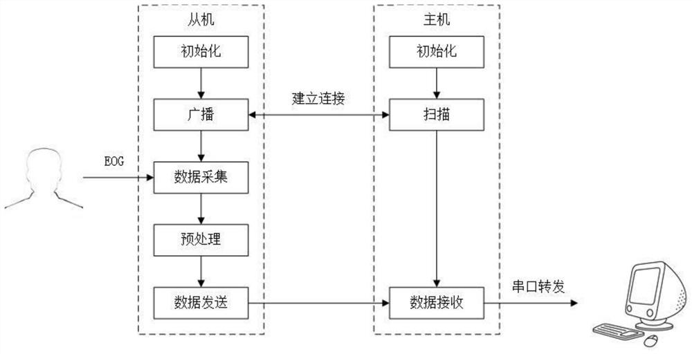
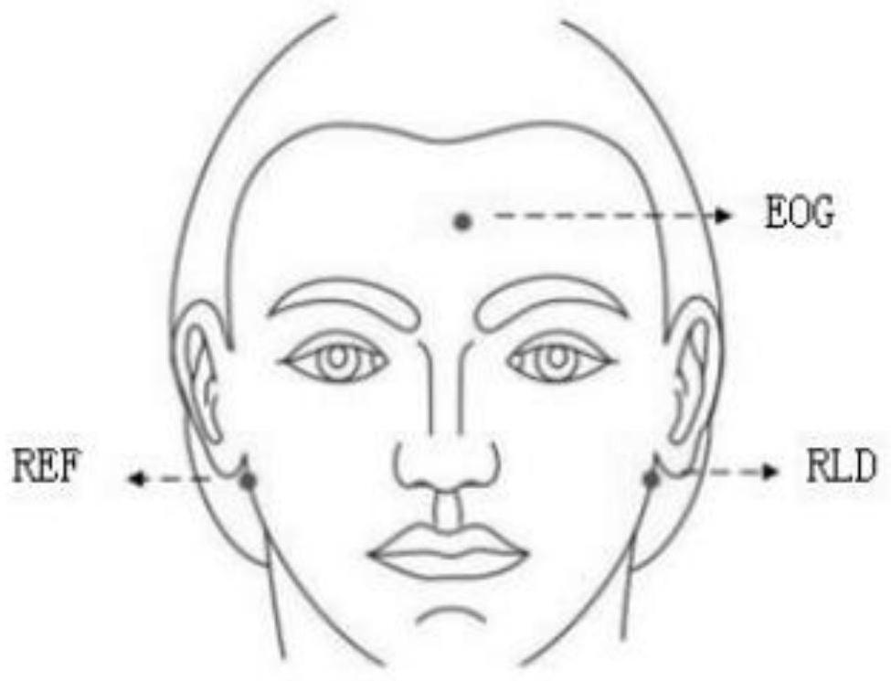
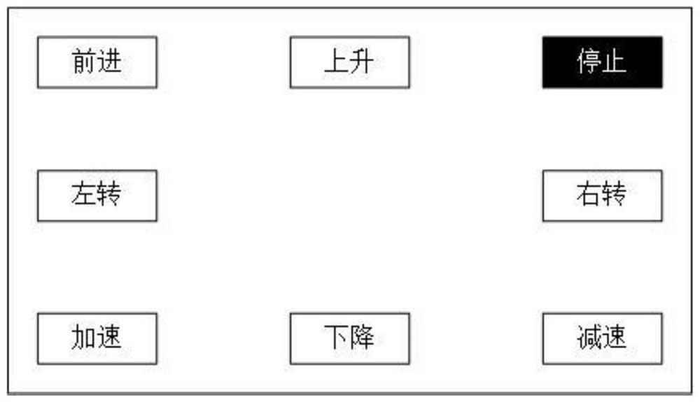
[0024] see Figure 1 to Figure 3 , the present invention provides a technical solution: an unmanned aerial vehicle control system based on a portable oculoelectric collection device. It consists of two parts, and wireless communication is used for information transmission between the two. Commonly used short-distance wireless communication protocols include Wi-Fi, Bluetooth, ZigBee, and NFC. Here, Bluetooth communication is used as an example; the master-slave establishes a connection and data The communication process is as figure 1 As shown; the master-slave processing chip takes the model CC2640 as an example. Both need to initialize the process after power-on, including clock initialization, on-board peripheral initialization, and Bluetooth GAP layer and GATT layer initialization. Then the slave machine enters the broadcast state, and sends broadcast packets in the three broadcast channels of the 2.4GHz frequency band, including the device name, UUID, and device address o...


PUM


Abstract

The invention discloses an unmanned aerial vehicle control system based on a portable electro-oculogram acquisition device, the system comprises the electro-oculogram acquisition device, an electro-oculogram stimulation module and an unmanned aerial vehicle module, the electro-oculogram acquisition device is composed of a master machine and a slave machine, information transmission is carried out between the master machine and the slave machine in a wireless communication mode, and the near field wireless communication mode comprises Wi-Fi, Bluetooth, ZigBee and NFC. According to the portable electro-oculogram acquisition device, the unmanned aerial vehicle is controlled, the problems that traditional electro-oculogram acquisition equipment is not easy to carry and complex to operate are solved, and efficient control over the unmanned aerial vehicle can be achieved in combination with proposed electro-oculogram training and recognition algorithms; an aircraft is controlled through electro-oculogram signals, a traditional manual control mode is eliminated, the problem that two hands cannot execute a plurality of instructions at the same time can be solved through a manual control and eye control mode, the control flexibility and diversity are improved, and people with two-hand dyskinesia can be benefited by purely adopting the eye control mode; the system has wide application prospects in the flight control field, the disabled assisting field and the education field.

Description

technical field [0001] The invention belongs to the technical field of flight control, and in particular relates to an unmanned aerial vehicle control system based on a portable oculoelectric collection device. Background technique [0002] The invention patent with the application number of 201710256131.X designs a system and method for searching aircraft in three-dimensional space based on EEG and EEG signals. The aircraft is controlled by combining EEG signals and EEG signals. The MI (motor imagery) signal is used as a decision-making subsystem, and the blink signal in the eye contact is used as an interface conversion subsystem. Blinking can switch the vertical and horizontal MI task interfaces, and then control the left and right yaw and vertical lift of the aircraft through the motor imagery behavior of the left and right hands. . The control mode of the system has better control diversity and scene adaptability, but the control method is more complicated, and the use...

Claims


Application Information

Patent Timeline
Patent Type & Authority Applications(China)
IPC IPC(8): G05D1/10
CPCG05D1/101
Inventor 李远清丁凌崧瞿军
Owner SOUTH CHINA UNIV OF TECH
Learn More