
Zinc negative electrode provided with electrolyte flow distribution component and application thereof

An electrolyte and zinc negative electrode technology, which is applied in the field of zinc negative electrodes, can solve the problems of increasing battery internal resistance and decreasing battery charge and discharge efficiency, and achieves the effect of optimizing the electrolyte flow channel

Inactive Publication Date: 2021-06-04
上海簇睿低碳能源技术有限公司
View PDF3 Cites 0 Cited by
  • Summary
  • Abstract
  • Description
  • Claims
  • Application Information

AI Technical Summary

Problems solved by technology

Although the above method can physically block the direction of dendrite growth, the addition of separators and coating materials will inevitably increase the internal resistance of the battery, which will lead to a decrease in the charge and discharge efficiency of the battery.

Method used


Image

  • Zinc negative electrode provided with electrolyte flow distribution component and application thereof
  • Zinc negative electrode provided with electrolyte flow distribution component and application thereof
  • Zinc negative electrode provided with electrolyte flow distribution component and application thereof

Examples


Embodiment 1

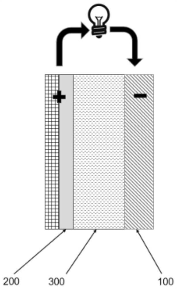
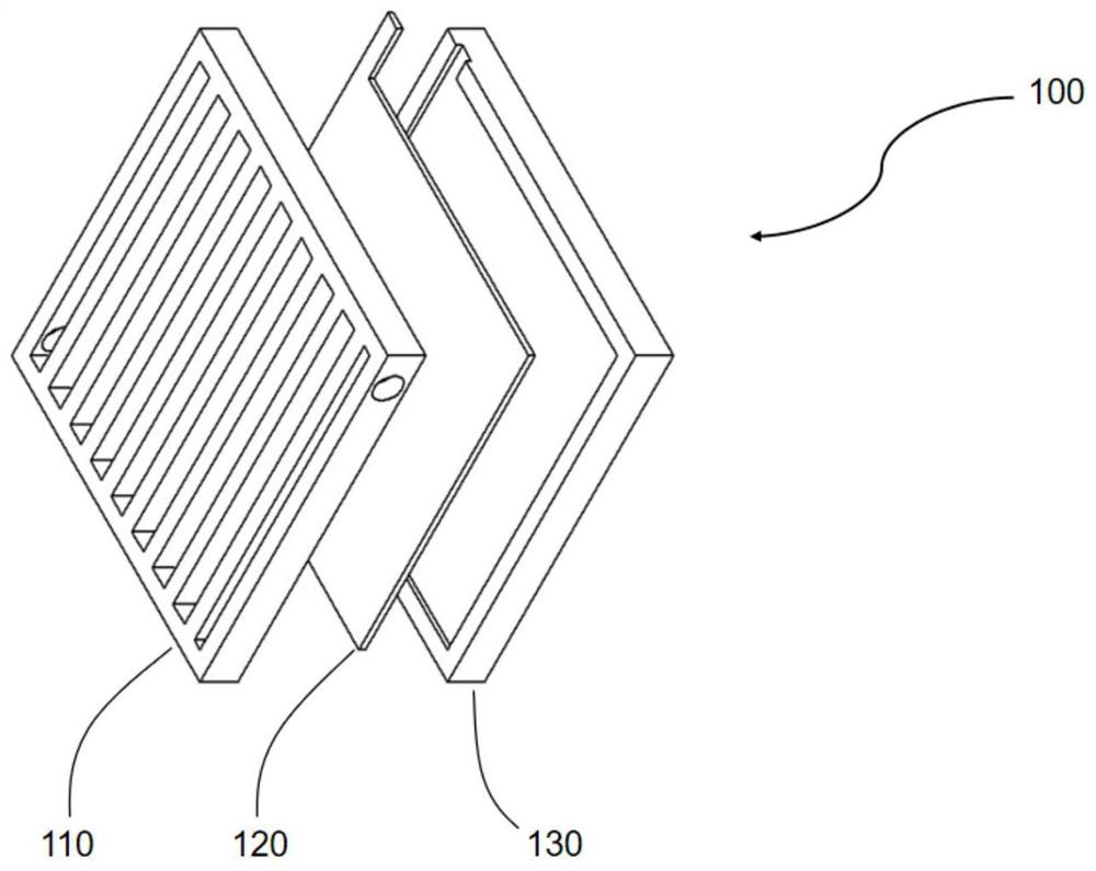
[0033] A zinc-air secondary battery, such as figure 1 As shown, it includes a zinc negative electrode 100 , an air positive electrode 200 and an electrolyte 300 . The zinc negative electrode 100 is a zinc plate provided with electrolyte flow distribution parts, the air positive electrode 200 is a metal mesh provided with a catalyst, the metal mesh acts as a current collector, and the electrolyte solution 300 can be sodium hydroxide or potassium hydroxide to provide hydrogen and oxygen Root ions participate in battery reactions. In addition, in the battery structure, end plates are usually provided on both sides of the positive and negative electrodes. The specific structure of the zinc negative electrode 100 is as follows: figure 2 As shown, it includes a zinc plate 120 with a current collection function, and one side of the zinc plate 120 is provided with an electrolyte flow distribution part 110, and the electrolyte flow distribution part 110 is a grid structure with a fr...

Embodiment 2

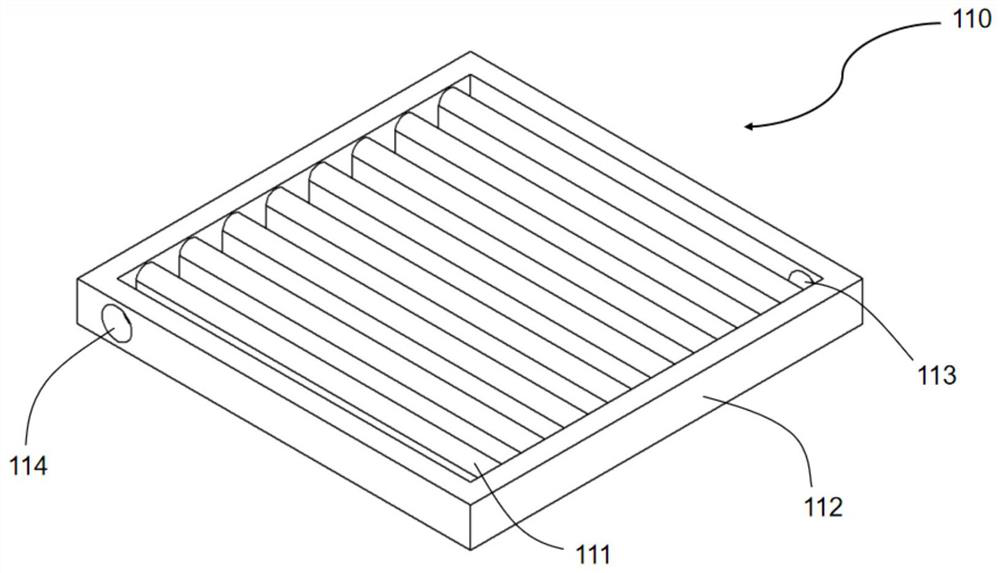
[0037] The structure of the zinc-air secondary battery of this embodiment is the same as that of Embodiment 1, the difference is that in the electrolyte flow distribution part 110 of this embodiment, the guide column 111 is close to the zinc plate 120, and the guide column 111 has only One end is connected to the frame 112 and the ends of the adjacent guide columns connected to the frame 112 are staggered, so the electrolyte 300 has a serpentine flow channel when flowing on the surface of the zinc plate 120, and the electrolyte 300 flows when flowing through the surface of the zinc plate 120 The direction will be constantly changing, as in Figure 6 indicated by the arrow in .

[0038] The battery system is placed vertically. When the battery is charging and discharging, the electrolyte 300 enters the electrolyte flow distribution part 110 from the inlet 113 of the frame and fills the gap of the grid structure, and then flows out from the electrolyte outlet 114, and the electr...


PUM


Abstract

The invention discloses a zinc negative electrode provided with an electrolyte flow distribution component and application thereof. The zinc negative electrode comprises a zinc plate (120) with a current acquisition function, one side of the zinc plate (120) is provided with an electrolyte flow distribution part (110), the electrolyte flow distribution part (110) comprises a plurality of diversion columns (111) and a frame (112), the diversion columns (111) are arranged in the frame (112), and the opposite angles of the frame (112) are respectively provided with an electrolyte inlet (113) and an electrolyte outlet (114) higher than the electrolyte inlet (113). The electrolyte flow distribution part changes the flow mode of the electrolyte on the surface of the zinc plate, so that dendritic crystals are not easy to gather on the surface of the zinc electrode, and meanwhile, the internal resistance of a battery is not increased; and therefore, the stability and utilization rate of the battery are effectively improved.

Description

technical field [0001] The invention relates to a zinc negative electrode provided with an electrolyte flow distribution part and an application thereof, belonging to the technical field of new energy storage. Background technique [0002] Zinc-air battery is a battery technology that uses metal zinc and oxygen in the air to perform an electrochemical reaction to achieve energy storage. Zinc-air batteries have been widely used in the market as primary batteries (non-rechargeable), and the technology is relatively mature. Its characteristics of no noise, small size, and high energy density make zinc-air batteries widely used in hearing aids, cameras and other small silent electronic devices. Generally, zinc-air batteries are composed of positive electrodes, negative electrodes, electrolytes, diaphragm materials, and outsourcing materials. The positive electrode of the battery is an air electrode, which is directly exposed to the air. The negative electrode of the battery i...

Claims


Application Information

Patent Timeline
Patent Type & Authority Applications(China)
IPC IPC(8): H01M8/0263H01M8/0273H01M10/42H01M12/08
CPCH01M8/0263H01M8/0273H01M10/4235H01M12/08Y02E60/10Y02E60/50
Inventor 孙予罕王慧白玉佳刘一健赵唱
Owner 上海簇睿低碳能源技术有限公司
Learn More