A kind of ultra-low pressure membrane separation system and separation method

A separation system and separation method technology, applied in ultra-low pressure membrane separation system and separation field, can solve the problems of increased final benefit, increased adsorption effect and non-specific interception, reduced macroscopic filtration efficiency of membrane fluid, etc., to achieve improved separation efficiency , The effect of shortening the separation time

Active Publication Date: 2021-11-26
杭州佰迈医疗科技有限公司
View PDF8 Cites 0 Cited by
  • Summary
  • Abstract
  • Description
  • Claims
  • Application Information

AI Technical Summary

Problems solved by technology

However, microporous membranes such as chemical membranes or nuclear pore membranes are limited by the support strength and pore size precision. Increasing the membrane pore size has to reduce the porosity of the membrane, so the actual macroscopic filtration efficiency of the fluid passing through the membrane may be reduced instead. If these adsorption effects and non-specific interception are increased, the ultimate benefit of separating clinical or biological samples by ultra-low pressure membranes may not be increased.
Therefore, the existing membrane separation system is unable to perform high-precision, effective and non-destructive separation of cell subpopulations with certain size or stiffness characteristics.
[0006] In addition, the existing membrane separation technology generally requires a large membrane pressure to ensure the filtration flux. Conventional microfiltration or ultrafiltration is generally carried out under a pressure above MPa to ensure a certain filtration rate and a stable filtration rate of the sample. membrane scale

Method used


Image

  • A kind of ultra-low pressure membrane separation system and separation method
  • A kind of ultra-low pressure membrane separation system and separation method
  • A kind of ultra-low pressure membrane separation system and separation method

Examples


Embodiment 1

[0043] Such as Figure 11 As shown, an ultra-low pressure membrane separation system includes an ultra-low pressure generating device, a membrane scaling control module, a flow rate control device, and a pressure detection device; the ultra-low pressure generating device is configured to provide The required ultra-low pressure, the ultra-low pressure is between 0.01KPa and 40KPa; the membrane scale control module is configured to keep the membrane scale layer in a single layer or loose state; the flow rate control device is configured to The flow rate of the sample to be filtered can be controlled, and the pressure detection device is configured to detect the pressure.

[0044] In some preferred modes, the ultra-low pressure generating device includes a filter membrane with low transmembrane resistance, a filter membrane packaging device, and a guide tube; the filter membrane is located between the package devices, and the guide tube 15 is connected to the package device. The...

Embodiment 2

[0100] Embodiment 2, with reference to attached Figure 1-5 .

[0101] Specifically, in this embodiment, as Figure 1-5 As shown, the packaging device includes a first fixing part 1, a second fixing part 2 and a sealing part 3, and the first fixing part 1 and the second fixing part 2 are configured to be able to cooperate for fixing and packaging the filter membrane; the sealing The element 3 is an elastic sealing element 3, and the elastic sealing element 3 is located between the first fixing element and the second fixing element, and the elastic sealing element 3 is configured to be able to seal the device, so as to prevent the sample to be filtered from flowing out laterally during filtering, and, The elastic seal has elasticity and can be deformed. When the elastic seal contacts with the filter membrane, it will not stab or damage the filter membrane, which is beneficial to ensure the smoothness of the filter membrane surface. In some preferred manners, the sealing membe...

Embodiment 3

[0128] Embodiment 3 is with reference to attached Figure 6 ,8.

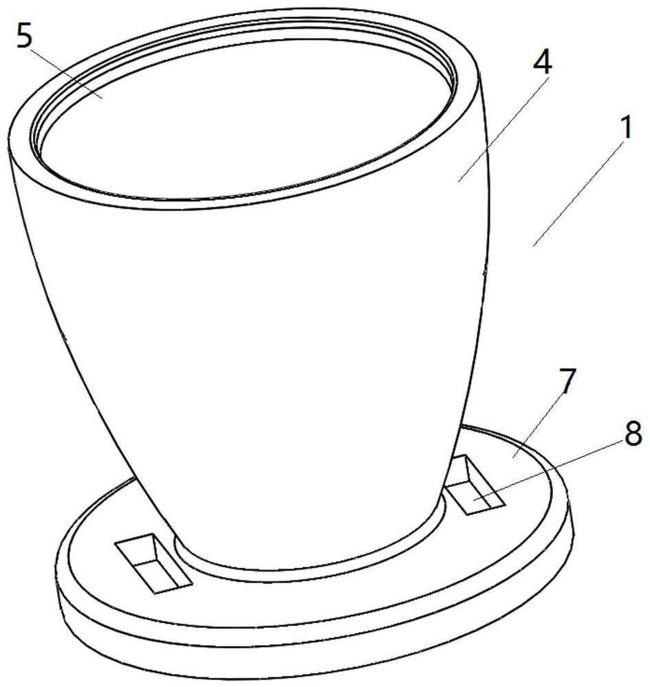
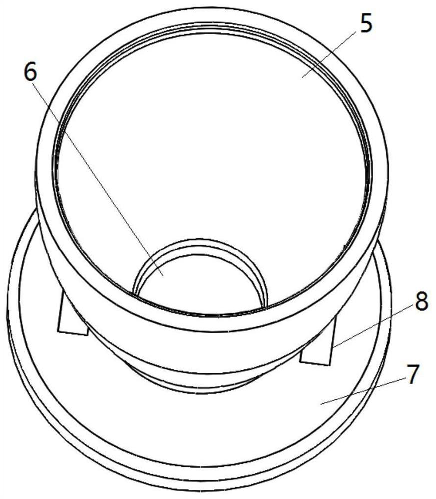
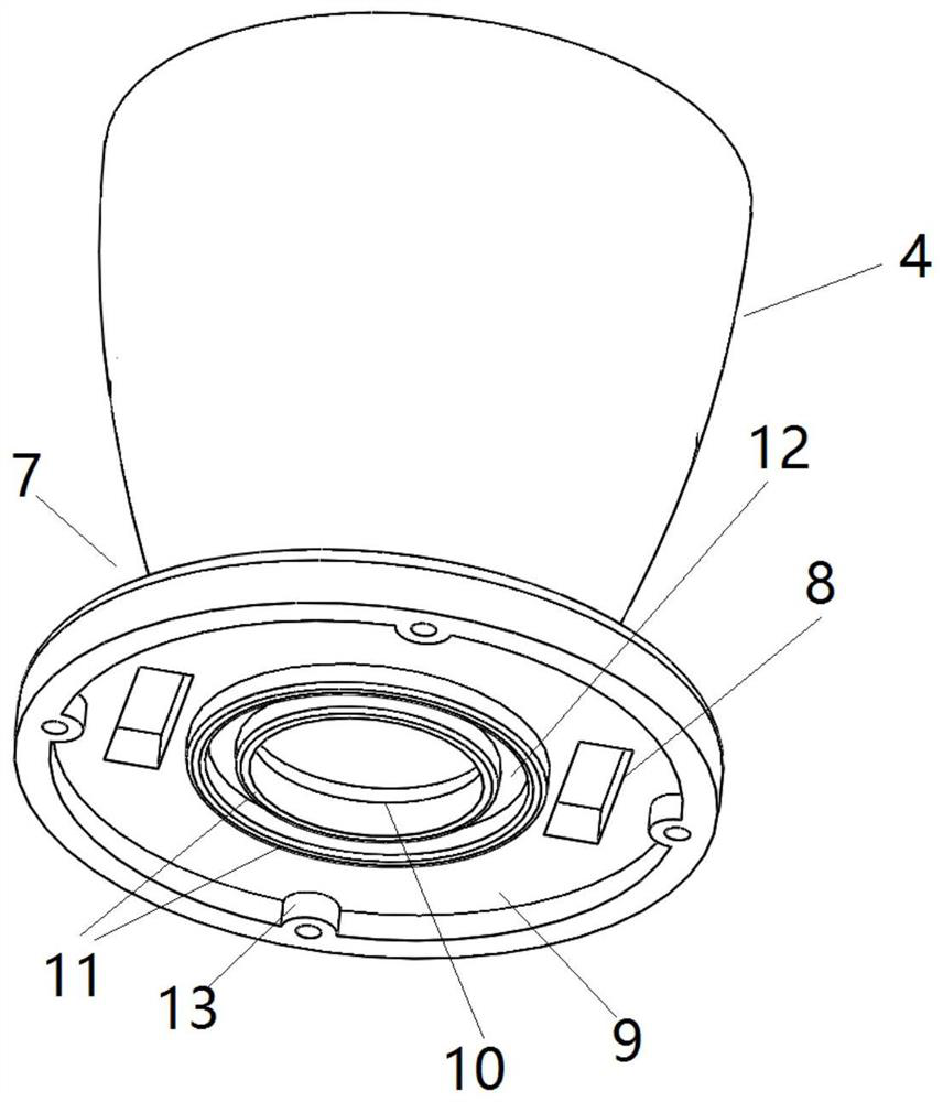
[0129] In this example, if Figure 6 As shown, the first fixing member includes a first cavity 4 and a base, and the shape of the first cavity is similar to that of a cone. In other embodiments, the shape of the first cavity 4 may be cuboid, cube, cylinder or other shapes, and the present invention does not limit the specific shape of the first cavity. The size and shape of the first cavity will not affect the negative pressure under the membrane, but the height of the liquid to be filtered on the filter membrane should not be too high, otherwise a non-negligible positive pressure will be generated.

[0130] In some preferred manners, the upper section of the first cavity 4 is provided with a mounting portion for mounting a corresponding cover. The installation part may be an outwardly protruding rib or an inwardly recessed groove or a screw thread or a snap-fit ​​structure, or any other suitable structure fo...


PUM


Abstract

The invention discloses an ultra-low pressure membrane separation system, comprising an ultra-low pressure generating device, a membrane scale control module, a flow rate control device, and a pressure detection device; the ultra-low pressure generating device is configured to be used to provide The required ultra-low pressure, the ultra-low pressure is between 0.01KPa and 40KPa; the membrane scale control module is configured to keep the membrane scale layer in a single layer or loose state; the flow rate control device is configured In order to be able to control the flow rate of the sample to be filtered, the pressure detection device is configured to be able to detect the magnitude of the pressure. The invention also discloses an ultra-low pressure membrane separation method. The membrane separation system of the invention can accurately ensure the dynamic stability of the membrane separation system and control it at the ultra-low pressure separation level, and the system can be used to separate biological samples. The separation efficiency is improved, the separation time is shortened, and the cell state is not damaged or changed during the separation process.

Description

technical field [0001] The invention specifically relates to an ultra-low pressure membrane separation system and a separation method. Background technique [0002] From the perspective of clinical sample separation methodology, precise separation methods mainly include: density gradient centrifugation, microfluidic chip separation, flow cytometry, and magnetic bead sorting. Considering the essence of separation, there are two main types: (1) sieving by physical properties (such as density, hardness, size, shape, etc.), and (2) specific adsorption separation by biochemical properties. [0003] As a comprehensive separation method, membrane separation can separate target objects by physical or biochemical properties. The common membrane separation or membrane filtration field is divided into methods such as reverse osmosis filtration, nanofiltration, ultrafiltration and microfiltration. In the biological field, there are membrane separation methods such as separation of nucl...

Claims


Application Information

Patent Timeline
Patent Type & Authority Patents(China)
IPC IPC(8): B01D61/14
CPCB01D61/147
Inventor 马萧冯恩慧
Owner 杭州佰迈医疗科技有限公司
Why Eureka
Try Eureka