Speed reducer assembly

A technology of reducers and components, applied in transmission parts, belts/chains/gears, mechanical equipment, etc., can solve the problems of limiting the performance of mechanical arms, low integration, and large volume.

Inactive Publication Date: 2021-06-08
凡点(青岛)智能装备有限公司
View PDF0 Cites 0 Cited by
  • Summary
  • Abstract
  • Description
  • Claims
  • Application Information

AI Technical Summary

Problems solved by technology

At present, in the domestic market, the reducers for the joints of manipulators generally have problems such as large weight, low load capacity, large volume, and low integration, which limit the further improvement of the performance of the manipulator.

Method used


Image

  • Speed reducer assembly
  • Speed reducer assembly
  • Speed reducer assembly

Examples


Embodiment 1

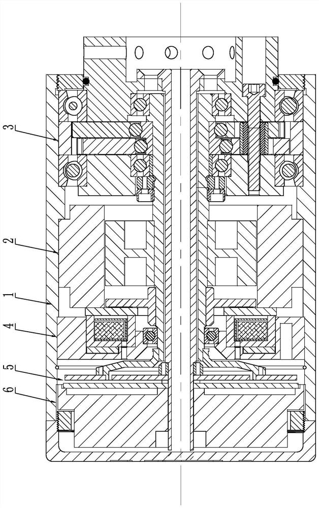
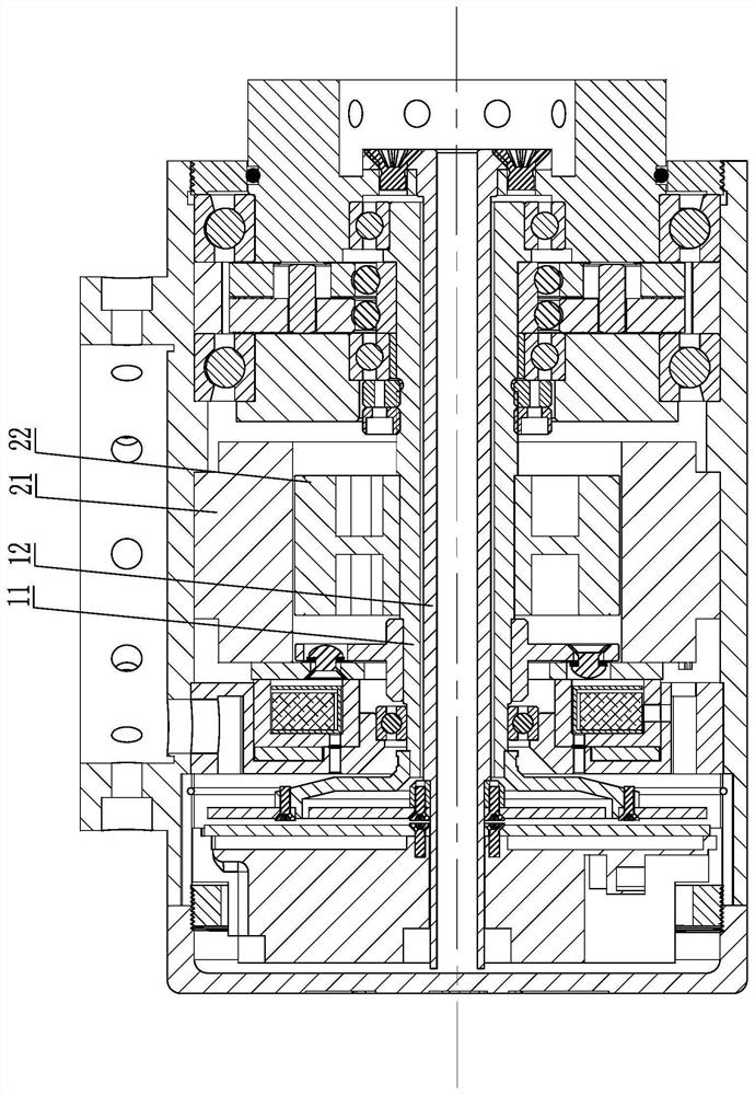
[0030] Such as figure 1 and figure 2 As shown, the joint of the manipulator includes the joint housing 1. The joint housing 1 is used as the installation carrier of the manipulator joint. It is formed by fastening a main housing and a side end cover. The main housing and the side end cover The covers can be threaded or screwed. A motor assembly 2, a reducer assembly 3, a brake assembly 4, an encoder assembly 5, and a drive assembly 6 are installed in the joint housing 1, and each assembly is arranged inside the joint housing 1 to form an integrated joint structure; The joint housing 1 is provided with a housing mounting seat for connecting the joint of the mechanical arm to the mechanical arm, and the housing mounting seat is a mounting flange; the surface of the joint housing 1 is provided with a wire passing through The hole is arranged inside the installation flange, which can facilitate the connection with other mechanical arms and avoid the leakage of the wire hole.

...

Embodiment 2

[0049] The difference between the second embodiment and other embodiments is that the structure of the bearing eccentric sleeve is different, and other structures are the same.

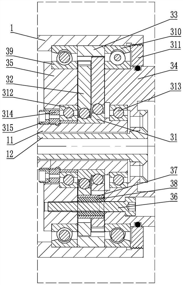
[0050] The bearing eccentric sleeve in Embodiment 1 has an integral structure, see image 3 , that is, the outer circumference of a bearing eccentric sleeve is equipped with two transmission gears through two bearing balls, and in this embodiment, the bearing eccentric sleeve includes N eccentric bearings sequentially installed on the power output and output shaft, N≥ 2. The phase angle between adjacent eccentric bearings is 360° / N, and an eccentric installation position is formed on the outer circumference of each eccentric bearing, see Figure 4 The intermediate reducer assembly is provided with three eccentric bearings, the phase angle between the three eccentric bearings is 120°, and each eccentric bearing is equipped with a transmission gear, that is, the number of transmission gears corresponds ...

Embodiment 3

[0052] The difference between the third embodiment and other embodiments is that the structure of the pin sleeve 37 is different, and the other structures are the same.

[0053] The pin bushing in Embodiment 1 has an integrally formed structure, see image 3 , because the phase angles of the two transmission gears are different, that is, the direction of the force acting on the pin sleeve when the two transmission gears move is different, so that there is a tangential torque in the pin sleeve, and this torque causes the transmission gear and the pin shaft to The friction between the sleeves is relatively large, which will reduce the efficiency of torque transmission. In order to solve this problem, the pin sleeve is set as a segmented structure, see Figure 4 , in this embodiment, the pin sleeve includes at least two sub-sleeves that are sequentially connected, the number of the sub-sleeves corresponds to the number of the transmission gears, and the outer circumference of eac...


PUM


Abstract

The invention discloses a speed reducer assembly. The speed reducer assembly comprises a bearing eccentric sleeve fixedly mounted on a power input shaft, N eccentric mounting positions with different phase angles are arranged on the periphery of the bearing eccentric sleeve, the phase angle between every two adjacent eccentric mounting positions is 360 degrees / N, and N is larger than or equal to 2. A transmission gear is rotationally mounted on each eccentric mounting position, and a fixed gear ring is engaged with the periphery of each of all the transmission gears. The speed reducer assembly further comprises a planet carrier upper cover and a planet carrier lower cover which are in coaxial cooperation, and an anti-loose fixing device for fixing all the transmission gears inside is connected between the planet carrier upper cover and the planet carrier lower cover. The anti-loose fixing device is used for integrally mounting the planet carrier upper cover, the transmission gears and the planet carrier lower cover. Anti-loose bolts and pin shafts are connected through glue injection, so that the assembly errors between the anti-loose bolts and the pin shafts are eliminated, and the machining precision is improved. The speed reducer assembly further has the advantages of being light, compact in structure, high in integration level, low in rotating speed, high in torque, high in reliability and the like.

Description

technical field [0001] The invention relates to the technical field of reducers, in particular to a reducer assembly for a mechanical arm joint. Background technique [0002] With the rapid development of industrial automation technology, robots, as an important industrial automation equipment, are getting more and more attention, and their applications are becoming more and more extensive. Robot technology mainly concentrates the latest research results of various technologies such as mechanical engineering, automatic control and artificial intelligence, embodies the latest achievements of optoelectronic integration, and is one of the most active fields in the development of contemporary science and technology. The robotic arm is currently the most widely used automated mechanical device in the field of robotics. It plays an extremely important role in production and life. In practical applications, many industrial processes require robotic arms for assembly and extraction ...

Claims


Application Information

Patent Timeline
Patent Type & Authority Applications(China)
IPC IPC(8): F16H57/08
CPCF16H57/08F16H57/10
Inventor 石东海
Owner 凡点(青岛)智能装备有限公司
Why Eureka
Try Eureka