Dust raising station auxiliary monitoring device

A monitoring device and dust-raising station technology, which can be applied to measuring devices, supporting machines, mechanical equipment, etc., can solve the problems of troublesome, inaccurate, and high input costs in monitoring, and achieve the effects of accurate and effective data, good operating environment, and convenient movement.

Active Publication Date: 2021-06-08
李健
View PDF12 Cites 4 Cited by
  • Summary
  • Abstract
  • Description
  • Claims
  • Application Information

AI Technical Summary

Problems solved by technology

[0003] In order to effectively detect the urban dust situation, basically every city will set up a dust station as an air detection place. The existing dust device basically stays at the stage of air particle capture, that is, by detecting the number of dust particles in a unit area, In order to judge its particle concentration, in order to understand the quality of the air, but the processing equipment of this method is relatively backward, and it is often not only troublesome to monitor, but also has inaccurate problems, which is not conducive to the detection of urban environment
[0004] In addition, affected by the natural environment and human factors, the concentration of particles in different areas is often different. The existing treatment method is to arrange corresponding facilities in multiple areas. On the one hand, the investment cost is high, and on the other hand, it is not easy to manage and maintain

Method used


Image

  • Dust raising station auxiliary monitoring device
  • Dust raising station auxiliary monitoring device
  • Dust raising station auxiliary monitoring device

Examples


Embodiment Construction

[0028] The following will clearly and completely describe the technical solutions in the embodiments of the present invention with reference to the accompanying drawings in the embodiments of the present invention. Obviously, the described embodiments are only some, not all, embodiments of the present invention. Based on the embodiments of the present invention, all other embodiments obtained by persons of ordinary skill in the art without making creative efforts belong to the protection scope of the present invention.

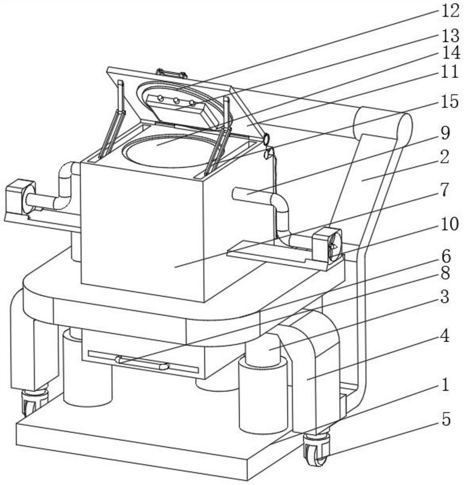
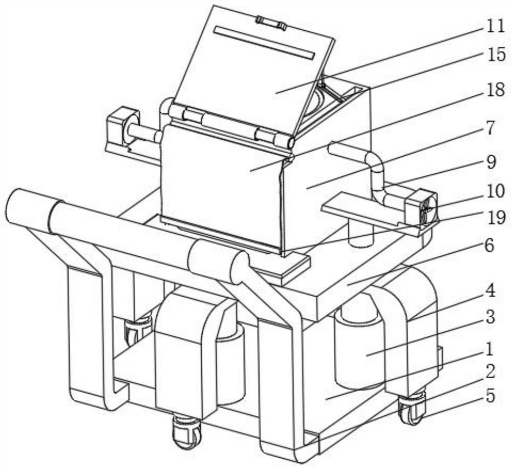
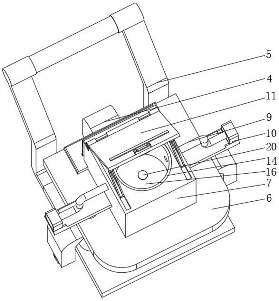
[0029] Such as Figure 1 to Figure 8 As shown, the present invention provides an auxiliary monitoring device for a dust raising station, which includes a base plate 1 and an annular plate 6, a detection box 7 is fixedly installed in the middle of the inner portion of the annular plate 6, and a pumping plate 8 is movably clamped at the lower end of the detection box 7. And the upper end of detection box 7 both sides is all fixedly installed with exhaust pipe 9,...


PUM


Abstract

The invention belongs to the technical field of environment monitoring, and discloses a dust raising station auxiliary monitoring device which comprises a base plate and an annular plate. A detection box is fixedly installed in the middle of the interior of the annular plate, a drawing plate is movably connected to the lower end of the interior of the detection box in a clamped mode, and exhaust pipes are fixedly installed at the upper ends of the two sides of the detection box. Exhaust fans are fixedly mounted on the outer sides of the two exhaust pipes, a hinge cover is fixedly mounted at the top of the detection box, a sealing disc is fixedly mounted in the middle of the bottom of the hinge cover, and an illuminance sensor is fixedly mounted in the middle of the bottom of the sealing disc. The purpose of accurate detection is achieved by arranging the detector, the detection box, the illuminance sensor and the like, ambient air needing to be detected always uniformly enters the cavity by opening the hinge cover and utilizing the flowing of natural air, and a bent exhaust pipe, the hinge cover capable of being closed and covered and a drawing plate are arranged.

Description

technical field [0001] The invention belongs to the technical field of environmental monitoring, in particular to an auxiliary monitoring device for a dust raising station. Background technique [0002] Flying dust is an open pollution source that enters the atmosphere due to the dust on the ground being driven by wind, man-made or other drives. It is an important part of the total suspended particles in the ambient air. After the rain, use rainwater resources to immediately clean and wash the muddy water accumulated on the road. It is the most effective way to avoid the repeated formation of dust after the road soil is air-dried. At the same time, it can avoid the formation of dust by cleaning in sunny days, and it can also greatly save cleaning water. Adopting a reasonable road surface slope and road edge drainage design, using natural precipitation runoff to wash and clean road dust can achieve twice the result with half the effort in reducing dust pollution, and is an im...

Claims


Application Information

Patent Timeline
Patent Type & Authority Applications(China)
IPC IPC(8): G01N15/06B08B5/04F16M11/42F16M11/32
CPCG01N15/06B08B5/04F16M11/42F16M11/32G01N2015/0693
Inventor 李健
Owner 李健
Why Eureka
Try Eureka