Sintering flue gas circulation method and sintering flue gas circulation system

A technology of sintering flue gas and circulation system is applied in the field of sintering flue gas circulation method and sintering flue gas circulation system.

Pending Publication Date: 2021-06-11
BEIJING SHOUGANG INT ENG TECH
View PDF0 Cites 0 Cited by
  • Summary
  • Abstract
  • Description
  • Claims
  • Application Information

AI Technical Summary

Problems solved by technology

[0004] In order to solve the above technical problems, the present invention provides a sintering flue gas circulation method and a sintering flue gas circulation system to solve the technical problem of low flue gas circulation rate commonly existing in existing production

Method used


Image

  • Sintering flue gas circulation method and sintering flue gas circulation system
  • Sintering flue gas circulation method and sintering flue gas circulation system

Examples


Embodiment 1

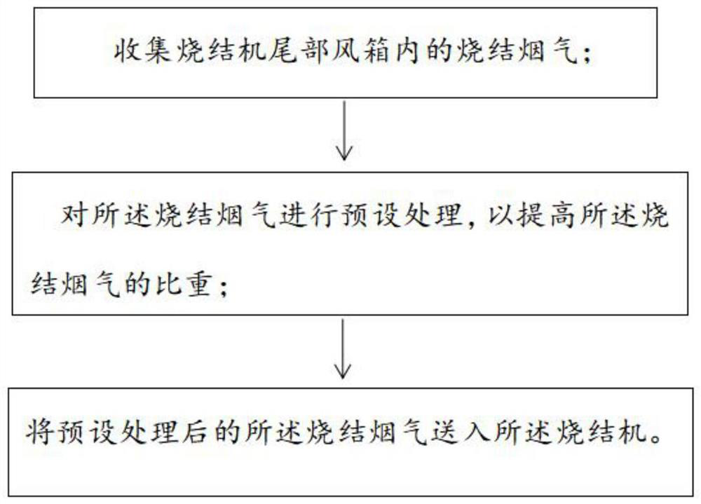
[0029] This embodiment provides a sintering flue gas circulation method, which sends the sintering flue gas that meets the recycling requirements to the sintering material layer after preset treatment to participate in combustion, so as to improve the circulation rate and absorption rate of the sintering flue gas. For details, see figure 1 , the sintering flue gas circulation method provided in this embodiment includes the following steps:

[0030] (1) Collect the sintering flue gas in the bellows at the tail of the sintering machine.

[0031] The study found that at the tail of the sintering machine, the sintering process is close to the end, so the oxygen content of the flue gas in the last few bellows is relatively high, and this part of the flue gas is collected and sent to the sintering material layer to participate in combustion, which can reduce the exhausted flue gas total amount. In this embodiment, the sintering flue gas in the wind box at the tail of the sintering...

Embodiment 2

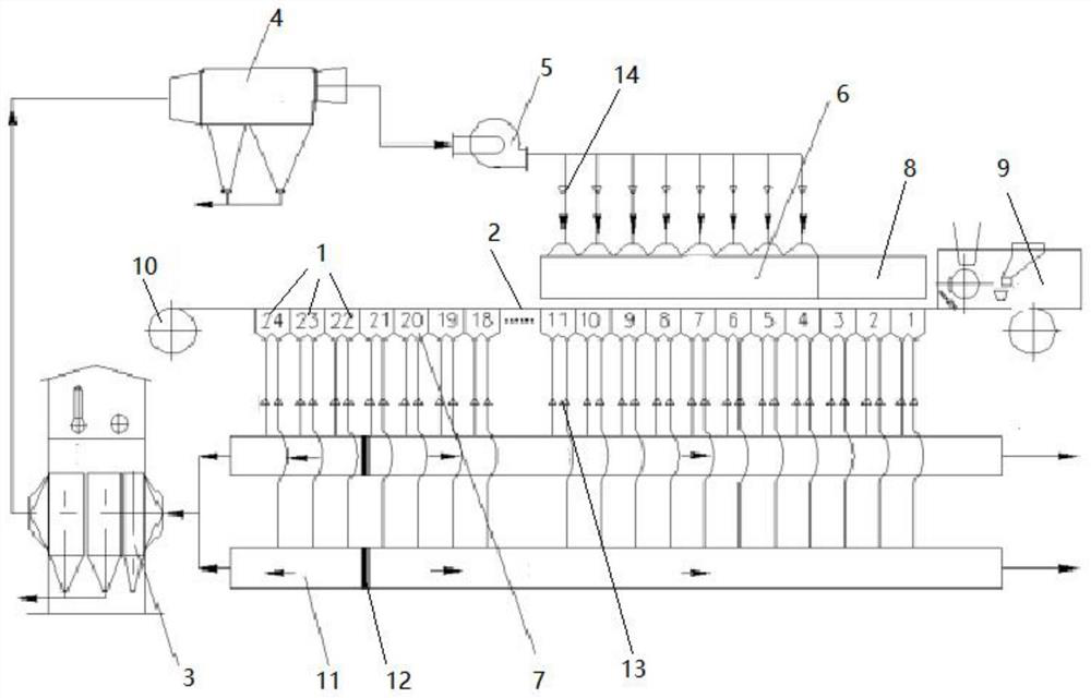
[0042] Based on the same inventive concept, this embodiment provides a sintering flue gas circulation system for implementing the sintering flue gas circulation method in the above-mentioned embodiment 1. For details, see figure 2 , the sintering flue gas circulation system includes a sintering machine and a circulation assembly; the sintering machine includes a tail bellows 1, a sintering machine body 2 and a hot air cover 6, the tail bellows 1 communicates with the sintering machine body 2 and the circulation assembly, and the hot air cover 6 is arranged on the sintering machine body 2 Above; the circulation component includes a flue gas treatment device and pipes. The flue gas treatment device is used to pre-process the sintering flue gas to increase the specific gravity of the sintering flue gas. The flue gas treatment device communicates with the tail wind box 1 and the hot air hood 6 through the pipe .

[0043] This embodiment does not specifically limit the flue gas t...


PUM


Abstract

The invention discloses a sintering flue gas circulation method and a sintering flue gas circulation system. The problem of low internal circulation rate of a sintering flue gas at present is solved, the condition that the circulating flue gas is completely absorbed by the material surface of a sintering pallet is ensured, and the total emission amount of the sintering flue gas is remarkably reduced. The sintering flue gas circulation method comprises the following steps of collecting the sintering flue gas in an air bellow at the tail of a sintering machine; carrying out preset treatment on the sintering flue gas to increase the specific gravity of the sintering flue gas; and feeding the sintering flue gas subjected to preset treatment into the sintering machine. According to the sintering flue gas circulation method provided by the invention, the sintering flue gas is subjected to preset treatment, so that the volume of the sintering flue gas is reduced, the specific gravity of the sintering flue gas is increased, the density of the flue gas is increased while the volume of the sintering flue gas is reduced, the flue gas is favorably absorbed by the material surface, the absorption rate of the sintering flue gas can be obviously increased, the total emission amount of the sintering flue gas is reduced, and the operation load of flue gas desulfurization and denitrification system equipment is reduced.

Description

technical field [0001] The invention relates to the technical field of iron and steel metallurgy sintering technology, in particular to a sintering flue gas circulation method and a sintering flue gas circulation system. Background technique [0002] The sintering process is the main source of energy consumption and pollutant emissions in steel production. During the sintering process, fuel combustion and mineral chemical reactions under high temperature conditions will produce a large amount of waste gas, which contains SO 2 , NOx, CO, CO 2 , Dioxins, dust and other pollutants have polluted the atmospheric environment. In recent years, in order to control environmental pollution, the country has continuously improved the emission standards of air pollutants in the iron and steel sintering and pelletizing industries. Some new technologies that are beneficial to environmental protection, energy saving and emission reduction have also been developed and applied, and the sinte...

Claims


Application Information

Patent Timeline
IPC IPC(8): F27D17/00
CPCF27D17/004F27D17/008
Inventor 姜凤春兰军
Owner BEIJING SHOUGANG INT ENG TECH
Why Eureka
Try Eureka