MRI image diagnosis device
A diagnostic device and imaging technology, which is applied in the field of medical devices, can solve the problems that the patient's body cannot be turned over by itself and cannot meet the diagnostic needs, and achieve the effects of meeting the diagnostic needs, good elasticity, and reducing the sense of resistance
- Summary
- Abstract
- Description
- Claims
- Application Information
AI Technical Summary
Problems solved by technology
Method used
Image

Examples
Embodiment 1
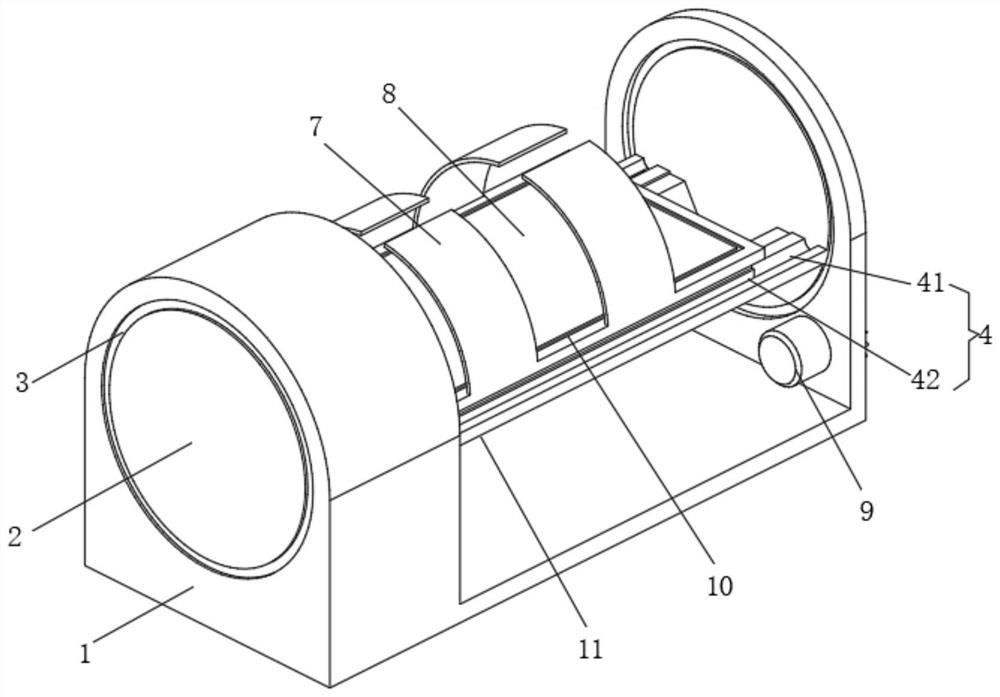
[0027] An MRI imaging diagnostic device, comprising a nuclear magnetic resonance body 1 and a servo motor 9;
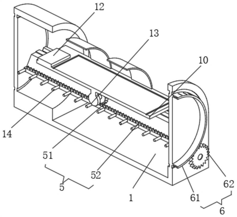
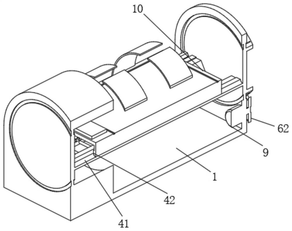
[0028] NMR body 1: the inner side is connected with the turntable 2 through the bearing 3, the inner side of the turntable 2 is fixed with the bed frame 11, the bed frame 11 is movably connected with the bed body 10 through the sliding mechanism 4, and the middle part of the bottom end of the bed body 10 is installed with a stepper Motor 13, the output shaft of stepping motor 13 is connected with bed frame 11 through the second transmission mechanism 5;
[0029] Servo motor 9: installed inside the nuclear magnetic resonance body 1, its output shaft is connected to the turntable 2 through the first transmission mechanism 6;
[0030] Among them, Velcro tapes 7 are also included, which are evenly distributed on the bed body 10, and the input ends of the servo motor 9 and the stepping motor 13 are electrically connected to the output ends of the external controller.
Embodiment 2
[0032] The difference between this embodiment and Embodiment 1 is:
[0033] In this embodiment, a memory pad 8 is also included, and the memory pad 8 is fixed on the top of the bed body 10. The memory pad 8 fixes the patient's body through automatic plasticity. It has good elasticity and comfort, and reduces the resistance of the patient. feel.
[0034] Also includes a memory pillow 12, the memory pillow 12 is fixed on the bed body 10 corresponding to the position of the head, the memory pillow 12 fixes the patient's head through automatic plasticity, has good elasticity and comfort, and reduces the patient's resistance feel.
Embodiment 3
[0036] The difference between this embodiment and Embodiment 1 is:
[0037] In this embodiment, the first transmission mechanism 6 includes a gear ring 61 and a first gear 62, the first gear 62 is fixed on the output shaft of the servo motor 9, the gear ring 61 is fixed on the end of the turntable 2, the gear ring 61 and the first gear A gear 62 meshes between teeth, the output shaft of the servo motor 9 drives the first gear 62 to rotate, the first gear 62 meshes with the gear ring 61 for transmission, the gear ring 61 drives the turntable 2 to rotate, and the turntable 2 drives the bed body 10 to rotate through the bed frame 11 , so that the body of the patient can be turned over, and the adjustment is convenient, so as to meet the needs of diagnosis.
[0038] The sliding mechanism 4 includes a chute 41 and a slide rail 42, the chute 41 is set on the bed frame 11, the slide rail 42 is fixed on the bottom of the bed body 10, the slide rail 42 is slidably connected to the insi...
PUM
 Abstract
Description
Claims
Application Information
 - R&D Engineer
- R&D Manager
- IP Professional
- Industry Leading Data Capabilities
- Powerful AI technology
- Patent DNA Extraction
Browse by: Latest US Patents, China's latest patents, Technical Efficacy Thesaurus, Application Domain, Technology Topic.
© 2024 PatSnap. All rights reserved.Legal|Privacy policy|Modern Slavery Act Transparency Statement|Sitemap