
Electroencephalogram acquisition system

An acquisition system and EEG technology, applied in medical science, sensors, diagnostic recording/measurement, etc., can solve the problems of poor stability and signal-to-noise ratio, weak anti-EMC ability, common-mode rejection ratio and electrical noise. Meet the actual requirements and other issues

Active Publication Date: 2021-06-18
ZHEJIANG PEARLCARE MEDICAL TECH
View PDF17 Cites 0 Cited by
  • Summary
  • Abstract
  • Description
  • Claims
  • Application Information

AI Technical Summary

Problems solved by technology

[0004] At present, most of the instruments on the market use instrumentation amplifiers with various amplifiers for multi-stage amplification to complete the acquisition of EEG physiological signals. The stability and signal-to-noise ratio are poor, and the anti-EMC ability is weak. Most of them can only be used for scientific research experiments and clinical applications. Poor use
At the same time, integrated chips are also used to complete EEG acquisition, mainly using the ADS129x series chips of American TI Company. This type of chip can complete multi-channel EEG signal acquisition and has a simple structure, but there are still many problems in the acquisition of EEG physiological signals.
[0005] Some of these integrated chips are only suitable for collecting electrophysiological signals. When collecting electrophysiological signals, the common mode rejection ratio and electrical noise cannot meet the actual requirements.
The EEG acquisition integrated chip launched by TI can only be used for EEG signal acquisition, and at the same time, there will be problems such as poor anti-EMC effect, baseline drift, and poor low-frequency stability.

Method used


Image

  • Electroencephalogram acquisition system
  • Electroencephalogram acquisition system

Examples


Embodiment

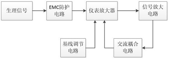
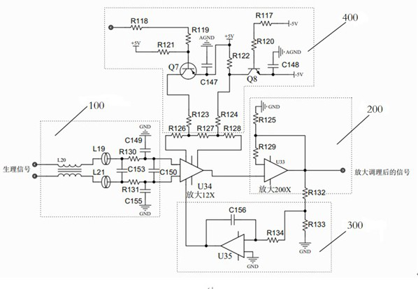
[0041] Such as figure 1 and figure 2 As shown, the embodiment of the present invention discloses an EEG acquisition system, including:

[0042] The EMC protection circuit 100 is used to receive the physiological signal of the forehead surface of the human body in real time, and convert the physiological signal into a current signal. The EMC protection circuit includes:

[0043] Common-mode inductor L20, the common-mode inductor L20 is used to receive the physiological signal of the biological brain, and filter the common-mode interference signal in the physiological signal, convert the physiological signal into a current signal, and divide the current signal into two paths, Among them, one current signal enters the first low-pass filter after the radiation interference introduced by the external connection is filtered by the magnetic bead L19; the other current signal enters the second low-pass filter after the radiation interference introduced by the external connection is ...


PUM


Abstract

The invention relates to an electroencephalogram acquisition system. The electroencephalogram acquisition system comprises an EMC protection circuit (100), an instrument amplifier, a signal amplification circuit (200) and an alternating current coupling circuit (300), wherein the EMC protection circuit (100) is used for receiving physiological signals of the forehead surface layer of the human body in real time and converting the physiological signals into current signals; the instrument amplifier is used for receiving the current signals processed by the EMC protection circuit and amplifying the current signals; the signal amplification circuit (200) is used for receiving the current signals amplified by the instrument amplifier and amplifying the current signals again so that the signal to noise ratio can be further increased; and the alternating current coupling circuit (300) is used for receiving the current signals amplified again, conducting high-pass filtering on the current signals and then coupling the current signals to the instrument amplifier so that a coupling loop with the high-pass filtering function can be formed. By means of the electroencephalogram acquisition system, the stability of electroencephalogram signal acquisition is enhanced, the overall noise level is reduced, and the signal to noise ratio of the overall acquisition circuit is greatly increased.

Description

technical field [0001] The invention relates to the collection of electroencephalogram physiological signals, which are used for extracting physiological electric signals on the forehead surface of a human body, in particular to an electroencephalogram acquisition system. Background technique [0002] At present, the acquisition of EEG vital signals worldwide is facing various technical challenges, mainly because EEG physiological signals are extremely weak signals and are easily affected by many external factors. The traditional EEG acquisition circuit structure is mostly implemented by conventional instrumentation amplifiers and multi-stage amplifier circuits. The circuit structure is complex, the overall signal-to-noise ratio is not high, and it is easily affected by factors such as baseline drift and high noise, and its stability is poor. The signal quality of the EEG physiological signal collection is poor, which brings great challenges and difficulties to the subsequen...

Claims


Application Information

Patent Timeline
IPC IPC(8): A61B5/369
Inventor 徐天昊陈瑞郁奕飞
Owner ZHEJIANG PEARLCARE MEDICAL TECH
Learn More