Energy-saving intelligent relay based on Internet of Things
A relay and energy-saving technology, which is applied in the field of energy-saving intelligent relays, can solve the problems of rising relay temperature control index, reducing relay performance, and inability to remotely control, etc., to achieve lower temperature control indicators, shorten breaking time, and simple structure Effect
- Summary
- Abstract
- Description
- Claims
- Application Information
AI Technical Summary
Problems solved by technology
Method used
Image
Examples
Embodiment 1
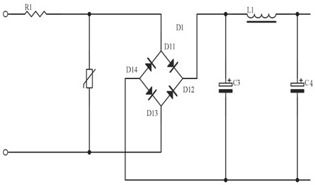
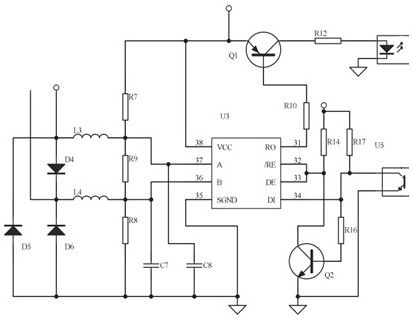
[0044] The present invention provides such Figure 1-Figure 5 An energy-saving smart relay based on the Internet of Things shown in , the control system includes a rectification filter circuit 91, a voltage conversion circuit 92 connected to the rectification filter circuit 91, a microcomputer control circuit 94 connected to the voltage conversion circuit 92, and The load output circuit 95 connected to the microcomputer control circuit 94, the communication circuit 93 connected to the microcomputer control circuit 94, in the present embodiment, the communication circuit 93 is provided with a communication module; the communication module includes a WIFI communication module, Cellular communication module and ZigBee module;
[0045] The rectification filter circuit 91 comprises a bridge rectifier diode D1, a pin connected to the band iron core inductor L1 on the bridge rectifier diode D1, capacitor C3 and capacitor C4 connected to both sides of the band iron core inductor L1; ...
Embodiment 2
[0074] The difference from Embodiment 1 is that in this embodiment, the structures of the two first main static contact plates 311 and the two second main static contact plates 321 are convoluted, and arc extinguishing plates are respectively provided in their cavities. Chamber 4, the first connecting static contact plate 411 and the second connecting static contact plate 421 are respectively provided with an arc extinguishing chamber 4, two first main static contact plates 311 and two second main static contact plates 321 and the first connection Near the static contact plate 411 and the second connected static contact plate 421, there are respectively permanent magnets 52, and 6 permanent magnets 52 are arranged in 2 columns and 3 rows, and the magnetic poles are arranged in N-S, S-N, N-S. According to the electromagnetic force orientation rule, The electromotive force designed to be 8 magnetic circuits perpendicular to the direction of the arc blows the arc to the arc exting...
PUM
 Abstract
Description
Claims
Application Information
 - R&D
- Intellectual Property
- Life Sciences
- Materials
- Tech Scout
- Unparalleled Data Quality
- Higher Quality Content
- 60% Fewer Hallucinations
Browse by: Latest US Patents, China's latest patents, Technical Efficacy Thesaurus, Application Domain, Technology Topic, Popular Technical Reports.
© 2025 PatSnap. All rights reserved.Legal|Privacy policy|Modern Slavery Act Transparency Statement|Sitemap|About US| Contact US: help@patsnap.com


