
Building decoration engineering wall surface processing device

A technology of architectural decoration engineering and processing equipment, which is applied in the direction of construction, building structure, stone processing equipment, etc., can solve the problems of manual control of slotting direction not vertical, many working environments for operators, and low work efficiency, etc., to achieve benefits Ease of use, increased processing quality, and labor-saving effects in the spraying process

Pending Publication Date: 2021-06-22
HENAN POLYTECHNIC INST
View PDF7 Cites 2 Cited by
  • Summary
  • Abstract
  • Description
  • Claims
  • Application Information

AI Technical Summary

Problems solved by technology

In these construction procedures, manual construction generally consumes manpower and time, so its work efficiency is not very high
At the same time, especially in the construction of the top of the wall, the staff also need to climb to a higher place with the help of ladders to perform operations, and the danger factor of these power tools itself makes the working environment of the operators more difficult. potential safety hazards, which can easily lead to safety accidents
More importantly, due to the randomness and uncertainty of manual work, there are often problems of inconsistent quality in the processed holes, holes, and grooves. It exists in the current building decoration project

Method used


Image

  • Building decoration engineering wall surface processing device
  • Building decoration engineering wall surface processing device
  • Building decoration engineering wall surface processing device

Examples


Embodiment 1

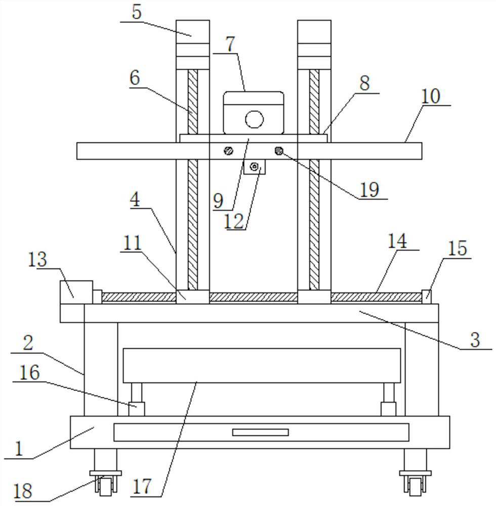
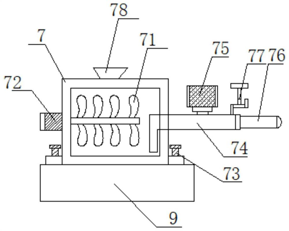
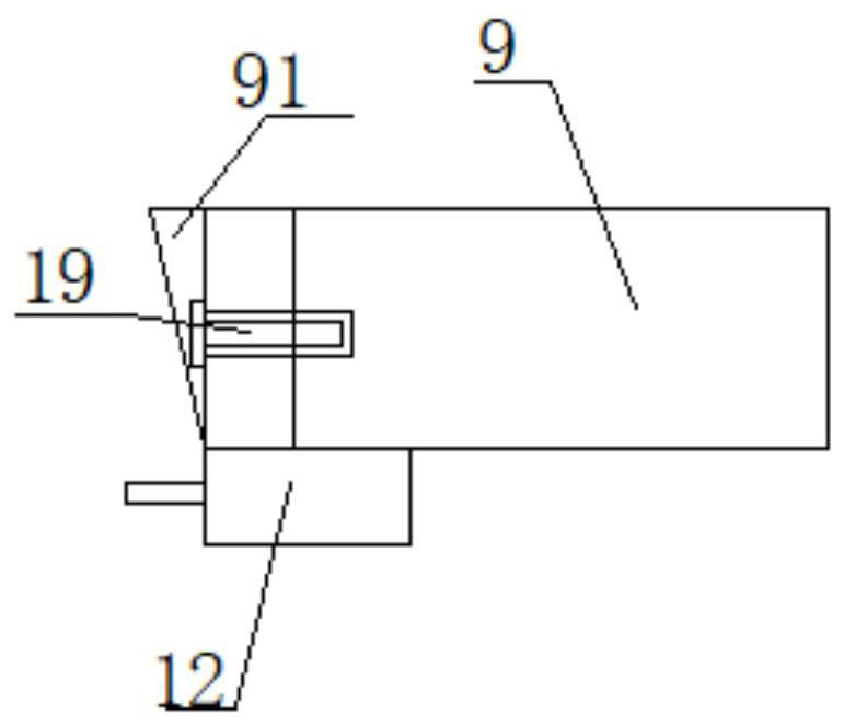
[0039] Such as Figure 1-4 As shown, the present invention proposes a wall surface processing device for architectural decoration engineering, including a device base 1, a machine column 2, a mobile processing table 3, a frame 4, a lifting motor 5, a lifting threaded rod 6, a paint mixing drum 7, and a mounting table Plate 9, scraper plate 10, T-shaped screw rod slider 11, scriber 12, screw motor 13, screw rod 14 and lifting platform 17; organic column 2 is installed on the two ends of device base 1, and is supported by machine column 2 Mobile processing table 3 is installed, and screw mandrel seat 15 is installed on the two ends of mobile processing table 3, and screw mandrel 14 is installed on the screw mandrel seat 15, and one end of mobile processing table 3 is installed with screw mandrel 14 driving connections. Screw motor 13, on the screw mandrel 14, T-shaped screw rod slider 11 is slidably installed, and the bottom of T-shaped screw screw slider 11 is slidably connecte...

Embodiment 2

[0054] Such as Figure 5-6 As shown, different from the wall surface processing device for building decoration engineering in Embodiment 1, the installation table 9 is installed with a drilling machine 20, and the drilling machine 20 is driven and connected with a drill bit 21.

[0055] When the present invention is in use, the staff removes the paint mixing drum 7 from the mounting platen 9, installs the drilling machine 20 on the mounting platen 9, installs the drill bit 21 on the drilling machine 20, and starts the screw mandrel The motor 13 drives the frame 4 to move horizontally on the screw rod 14 through the T-shaped screw rod slider 11, and moves to a suitable position. The lifting motor 5 is controlled by the controller to drive the installation table 9 through the lifting slide seat 8. The threaded rod 6 moves up and down, and the controller is electrically connected with the drilling machine 20 to control the drilling machine 20 to drive the drill bit 21. Different ...

Embodiment 3

[0057] Such as Figure 7-8 As shown, the wall surface processing device for building decoration engineering is different from that in Embodiment 1, and the feature is that a grinder 22 is installed on the installation platen 9 , and a grinding disc 23 is installed on the drive shaft of the grinder 22 .

[0058] When the present invention is in use, the staff will remove the drilling machine 20 from the mounting platen 9, install the grinding machine 22 on the mounting platen 9, install the grinding disc 23 on the grinding machine 22, and start the screw mandrel The motor 13 drives the frame 4 to move horizontally on the screw rod 14 through the T-shaped screw rod slider 11, and moves to a suitable position. The lifting motor 5 is controlled by the controller to drive the installation table 9 through the lifting slide seat 8. The threaded rod 6 moves up and down, and the controller is electrically connected with the grinder 22 to control the grinder 22 to drive the grinding dis...


PUM


Abstract

The invention belongs to the technical field of building tools, and discloses a building decoration engineering wall surface processing device which comprises a device base, a movable processing table, a rack, a lifting motor, lifting threaded rods, a coating stirring barrel, a mounting table plate and lead screws. Machine columns are installed at the two ends of the device base, the movable processing table is installed through the machine columns in a supporting mode, lead screw bases are installed at the two ends of the movable processing table, the lead screws are installed on the lead screw bases, lead screw motors in driving connection with the lead screws are installed at one end of the movable processing table, and T-shaped lead screw sliding blocks are installed on the lead screws in a sliding mode. The rack is fixedly mounted at the tops of the T-shaped lead screw sliding blocks, the lifting threaded rods are mounted at the inner top and the inner bottom of the rack through threaded seats, and the lifting motor in driving connection with the lifting threaded rods is mounted at the top of the rack. According to the device, the lead screw motors and the screw rods are matched with the lifting motor and the lifting threaded rods, so that automatic scraping, scribing, spraying, drilling and polishing operations are realized; and the operation cost is reduced, and the building decoration quality is effectively improved.

Description

technical field [0001] The invention relates to the technical field of building tools, in particular to a wall surface processing device for building decoration engineering. Background technique [0002] In architectural decoration engineering, when constructing walls, it is necessary to carry out basic treatment, plaster leveling, gypsum board sticking bandages, scraping lime, grinding, brushing latex paint and wallpapering and other processes on the walls. The main process is to polish the walls after scraping lime If the dried white ash is not smooth enough, it will affect the subsequent process of painting latex paint and wallpapering. At present, it is necessary to manually open slots and holes in the corresponding positions of the wall for wiring in the grassroots treatment. However, there are problems when manually opening slots and holes. Due to the large size error, the slots and holes opened cannot meet the wiring requirements, and the grinding process is mainly do...

Claims


Application Information

Patent Timeline
Patent Type & Authority Applications(China)
IPC IPC(8): B24B7/18B24B41/02B24B41/04B24B47/20B28D1/14B28D7/00E04F21/00E04F21/16
CPCB24B7/182B24B41/02B24B41/04B24B47/20B28D1/146B28D7/00E04F21/00E04F21/16
Inventor 张志伟尤振陈静思刘莎刘胜芳
Owner HENAN POLYTECHNIC INST
Learn More