Gas phase epitaxy method

A vapor phase epitaxy and epitaxy technology, applied in chemical instruments and methods, electrical components, chemically reactive gases, etc., to achieve the effect of suppressing cross-contamination

Pending Publication Date: 2021-06-22
AZUR SPACE SOLAR POWER
View PDF8 Cites 0 Cited by
  • Summary
  • Abstract
  • Description
  • Claims
  • Application Information

AI Technical Summary

Problems solved by technology

[0005] Note also, however, that due to the reaction history there may also be additional undesired elements in the reaction chamber from previous processes
This can be problematic for producing low doped layers precisely

Method used


Image

  • Gas phase epitaxy method
  • Gas phase epitaxy method
  • Gas phase epitaxy method

Examples


Embodiment Construction

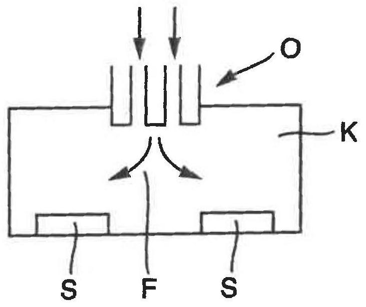
[0059] figure 1 A cross-section of a reaction chamber K of a vapor phase epitaxy facility is schematically shown. A substrate S is arranged on the bottom of the reaction chamber K. Furthermore, the reaction chamber K has a gas inlet part O through which the epitaxial flow F is introduced into the reaction chamber K.

[0060] The epitaxial flow F has a carrier gas, at least one first metal-organic precursor for elements of main group III (e.g. trimethylgallium, TMGa), a second precursor for elements of main group V (e.g. arsenic Hydrogen, Arsin) and a third precursor for the n-dopant (eg silane).

[0061] The gas inlet part O has a plurality of conduits terminating in the reaction chamber K, through which a component or components of the epitaxial gas flow F are each led to the reaction chamber K.

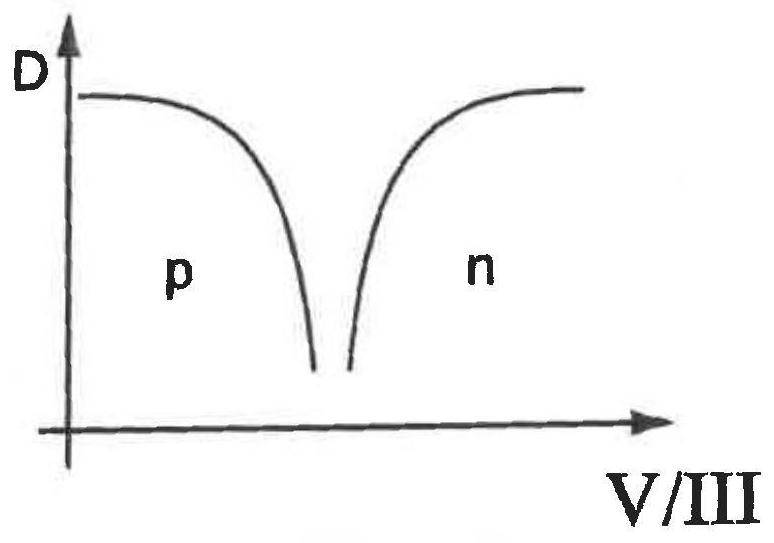
[0062] exist figure 2 The doping is plotted in a graph as a function of the amount ratio of the elements of the V. main group and the III. main group. In particular, not only ...


PUM


Abstract

The invention relates to a gas phase epitaxy method having the following method steps: growing a III-V layer having a doping changing from a first conductivity type to a second conductivity type on a surface or front layer of a substrate in a reaction chamber from a gas phase of an epitaxial gas stream, the epitaxial gas stream has a carrier gas, at least one first precursor for an element in the III. Main group, and at least one second precursor for an element in the V. main group, where the first growth height is reached and the second growth height is reached. A first doping initial value of the first conductivity type is set by means of a ratio of a first mass flow of the first precursor to a second mass flow of the second precursor in the epitaxial gas flow, and then the first doping initial value is reduced to a second doping initial value of the first conductivity type, the layer varies step by step or continuously across a transition region having a growth height of at least 10 [mu] m until a doping target value of the second conductivity type is reached.

Description

technical field [0001] The invention relates to a vapor phase epitaxy method. Background technique [0002] Various vapor phase epitaxy installations are known for the epitaxial production of semiconductor layers, for example the vapor phase epitaxy installation of the company Aixtron. [0003] What these installations have in common is that the epitaxial layer is deposited or grown from the vapor phase on the substrate introduced into the reaction chamber. For this, the reaction chamber is heated and an epitaxial gas flow is introduced into the reaction chamber. [0004] The composition of the gas flow depends on the type of layer to be grown, wherein typical precursors such as arsine and / or trimethylgallium provide the elements for the semiconductor layer to be grown and the doping of the layer is also added if necessary Precursors for dopants. The precursors are introduced into the reaction chamber by means of a carrier gas. To control the composition of the gas strea...

Claims


Application Information

Patent Timeline
Patent Type & Authority Applications(China)
IPC IPC(8): C30B29/40C30B29/42C30B25/02
CPCC30B29/40C30B29/42C30B25/02C30B25/165H01L21/0262H01L21/02576H01L21/02579H01L21/02546H01L21/02463H01L21/0251C30B25/14C30B25/18H01L21/02538H01L21/0257
Inventor C·瓦赫特G·凯勒D·富尔曼
Owner AZUR SPACE SOLAR POWER
Why Eureka
Try Eureka