
Distributed optical fiber light source control system suitable for wide temperature range

A distributed optical fiber and light source control technology, applied to thermometers, thermometers with physical/chemical changes, measuring devices, etc., to achieve the effects of reduced stability and simple temperature compensation

Pending Publication Date: 2021-06-22
CHINA COAL TECH & ENG GRP CHONGQING RES INST CO LTD +1
View PDF5 Cites 1 Cited by
  • Summary
  • Abstract
  • Description
  • Claims
  • Application Information

AI Technical Summary

Problems solved by technology

[0005] The invention provides a distributed optical fiber light source control system applicable to a wide temperature range, which solves the technical problem in the prior art that the average wavelength of the optical fiber light source can only be stabilized in a small working temperature range

Method used


Image

  • Distributed optical fiber light source control system suitable for wide temperature range
  • Distributed optical fiber light source control system suitable for wide temperature range

Examples


Embodiment 1

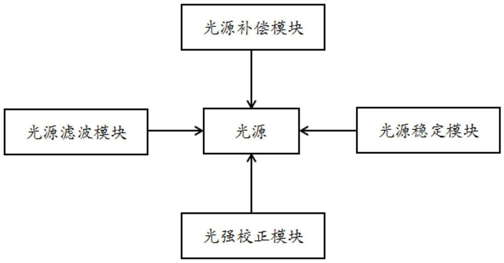
[0027] The embodiment is basically as attached figure 1 shown, including:

[0028] light source;

[0029] The light source filter module, the light source filter module includes a positive temperature coefficient long period fiber grating and a negative temperature coefficient long period fiber grating; wherein, the central wavelength of the positive temperature coefficient long period fiber grating increases with the temperature rise, and the average wavelength acting on the light source increases with the The decreasing interval when the temperature presents a parabolic change; the central wavelength of the long-period fiber grating with a negative temperature coefficient decreases as the temperature rises, and acts on the increasing area when the average wavelength of the light source presents a parabolic change with the temperature;

[0030] The light source compensation module is used to perform compensation calculation on each component of the light source according to ...

Embodiment 2

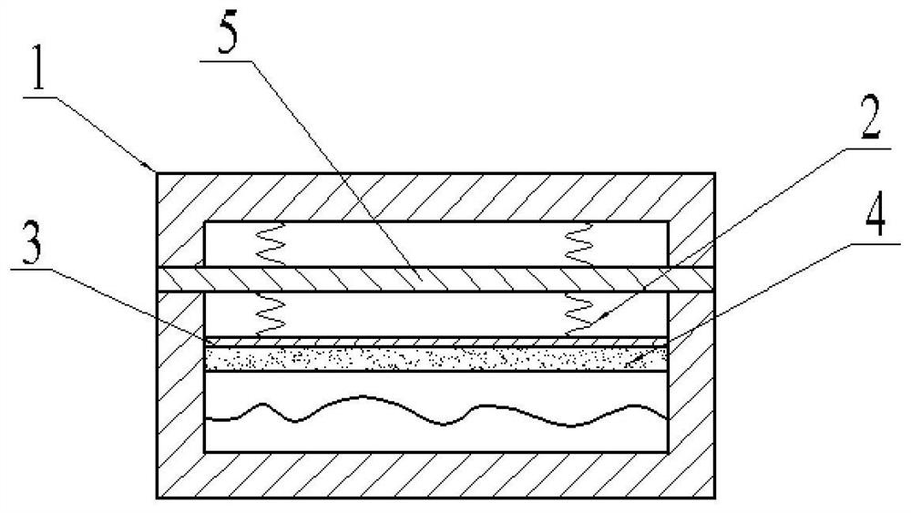
[0040] The only difference from Embodiment 1 is that it also includes a fixing groove and a protective shell, and the positive temperature coefficient long-period fiber grating and the negative temperature coefficient long-period fiber grating are fixed through the fixing groove, that is, the positive temperature coefficient long-period fiber grating and the negative temperature Coefficient long-period fiber gratings are fixed on the grooves to alleviate the effects of thermal expansion and contraction to prevent loosening. At the same time, a positive temperature coefficient long-period fiber grating and a negative temperature coefficient long-period fiber grating are arranged in sequence in the protective case, so as to protect the positive temperature coefficient long-period fiber grating and the negative temperature coefficient long-period fiber grating from water and dust. Protective effects.

Embodiment 3

[0042] The only difference from Embodiment 2 is that in this embodiment, the optical fiber 5 is used in winter in Northeast China, the daily temperature difference between day and night can be above 20-30°C, and the temperature change rate can reach 4-6°C / h; a part of the optical fiber 5 One is buried in the soil and the other is exposed to the air. Soil temperature will show seasonal fluctuations and diurnal changes with the change of air temperature near the surface; at the same time, due to the influence of periodic diurnal and annual changes in solar radiation, soil temperature will also change accordingly, making the annual change of soil temperature show It is a sinusoidal function, and the variation range of temperature decreases with the increase of soil depth. At a certain depth, the amplitude can be considered to be approximately zero. In addition, due to the different heat transfer coefficients of soil and air, the temperature of the soil is usually higher than that...


PUM


Abstract

The invention relates to the technical field of optical fiber sensor light sources, in particular to a distributed optical fiber light source control system suitable for a wide temperature range. The system comprises a light source; a light source filtering module which comprises a positive temperature coefficient long-period fiber grating and a negative temperature coefficient long-period fiber grating, wherein the central wavelength of the positive temperature coefficient long-period fiber grating is increased along with temperature rise, the average wavelength acting on the light source is in a progressively decreasing interval when the average wavelength is in parabolic change, the central wavelength of the negative temperature coefficient long-period fiber grating is reduced along with the rise of the temperature, and the average wavelength acting on the light source is in a progressively increasing interval when the average wavelength is in parabolic change; and a light source compensation module which is used for performing compensation calculation on each component of the light source according to a pre-established light source wavelength compensation model to obtain a compensation result of the light source wavelength and performing combination matching on each component according to a compensation result to obtain a finally selected component of the super light source. Temperature compensation can be carried out on the light source.

Description

technical field [0001] The invention relates to the technical field of optical fiber sensor light sources, in particular to a distributed optical fiber light source control system applicable to a wide temperature range. Background technique [0002] The light source is a key component of the fiber optic sensor, and the performance of the light source will also determine the performance of the fiber optic sensing system to some extent. For the superfluorescent fiber light source, especially the superfluorescent erbium-doped fiber light, compared with other broad-spectrum light sources, its average wavelength is stable, the output power is high, the spectral width is wide, and the coupling efficiency is high, so it has been widely used. Because the average wavelength of ordinary superfluorescent erbium-doped fiber light source will change with temperature, it is necessary to take measures to improve the stability of the average wavelength of superfluorescent fiber light source...

Claims


Application Information

Patent Timeline
Patent Type & Authority Applications(China)
IPC IPC(8): H05B47/10G01K11/3206
CPCH05B47/10G01K11/3206
Inventor 戴书球孙中光孙维张建鑫钟宇王璇谭一川梁帅彭迈罗剑
Owner CHINA COAL TECH & ENG GRP CHONGQING RES INST CO LTD
Learn More