Check patentability & draft patents in minutes with Patsnap Eureka AI!

Laser radar system based on micromirror array

A laser radar and micromirror array technology, applied in the field of radar, can solve the problems of limited clear aperture, restricting the system's ability to collect echo energy, etc., to achieve the effect of reducing impact, low cost and high signal strength

Pending Publication Date: 2021-06-25
觉芯电子(无锡)有限公司
View PDF9 Cites 10 Cited by
  • Summary
  • Abstract
  • Description
  • Claims
  • Application Information

AI Technical Summary

Problems solved by technology

However, the optical aperture of the system in which the transmitting and receiving optical paths are coaxial is very limited, which seriously restricts the system's ability to collect echo energy, so that the laser radar system can only work in short-distance situations.

Method used


Image

  • Laser radar system based on micromirror array
  • Laser radar system based on micromirror array
  • Laser radar system based on micromirror array

Examples


Embodiment 1

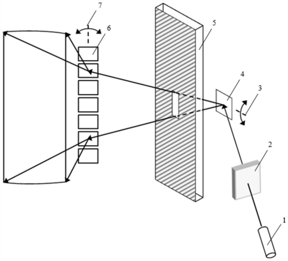
[0050] In view of the above-mentioned unresolved problems, the present invention proposes a laser radar system, which aims to realize long-distance detection with a compact structure and a high signal-to-noise ratio.

[0051] Such as figure 1 As shown, the laser light emitted by the laser 1 is collimated by the collimator lens 2 and then enters the vertical scanning micromirror 4 . The vertical scanning micromirror 4 is an electrostatically driven micromirror working in a quasi-static mode, which deflects and vibrates around the first rotating shaft 3, so that the incident laser beam scans within a certain angle in the vertical direction.

[0052] A reflective mirror 5 is arranged on the optical path of the laser beam, and the reflectivity of the reflective mirror 5 near the laser wavelength is close to 1. The reflector 5 only leaves a reflector light-transmitting area near the center, and the transmittance of the reflector light-transmitting area to the laser beam near the l...

Embodiment 2

[0064] In the foregoing embodiments, the vertical scanning micromirror 4 and the horizontal scanning micromirror array 6 are MEMS micromirror devices. It is made of SOI wafer and processed by semiconductor technology. The drive mode of the micromirror can be electrostatic drive, piezoelectric drive, electromagnetic drive, electrothermal drive, etc.

[0065] The vertical scanning micromirror 4 can adopt resonant scanning, quasi-static scanning or digital jump scanning.

[0066] The vertical scanning micromirror 4 can choose to use an electrostatically driven micromirror with planar comb teeth, or an electrostatically driven micromirror with a vertical comb tooth structure.

[0067] In a preferred example, the vertical scanning micromirror 4 is an electrostatically driven micromirror with a vertical comb structure.

[0068] The horizontal scanning micromirror array 6 can choose to use an electrostatically driven micromirror with a planar comb, or an electrostatically driven mi...

Embodiment 3

[0076] Such as image 3 As shown, in this embodiment, the width of the light-transmitting region of the reflector can be reduced, and a cylindrical mirror is formed on the light-transmitting region of the reflector, and the cylindrical mirror and the reflector form an integral body.

[0077] In a preferred example, an anti-reflection film is deposited on the outer surface of the cylindrical mirror, and a metal reflective layer is deposited on the area other than the cylindrical area.

[0078] The cylindrical lens structure can offset the diffraction effect that occurs when the laser passes through the light-transmitting area of ​​the mirror, ensuring good collimation of the laser beam.


PUM


Abstract

A laser radar system based on a micromirror array comprises a laser light source used for emitting a laser beam; a vertical scanning micromirror used for deflecting and vibrating along a first rotating shaft in a first driving mode, so that the laser beam scans in a first angle range in the vertical direction; a horizontal scanning micromirror array used for deflecting and vibrating along a second rotating shaft in a second driving mode, so that the laser beam scans in a second angle range in the horizontal direction; and a reflecting mirror arranged in a light path between the vertical scanning micromirror and the horizontal scanning micromirror array; The reflecting mirror is provided with a reflecting mirror light-transmitting area, and the reflecting mirror light-transmitting area just allows the laser beams within the first angle range to pass through.

Description

technical field [0001] The invention belongs to the field of radar, in particular to a laser radar system based on a MEMS micromirror array. Background technique [0002] LiDAR is a high-precision distance measurement device. Unlike multi-eye cameras, as an active detection device, lidar is not affected by lighting conditions and has strong anti-interference ability. In addition to applications in fields such as terrain mapping, it has also attracted great attention in the fields of autonomous driving and 3D imaging in recent years. Traditional lidar uses multiple lasers combined with the design of mechanical rotating structure, which is not only slow and bulky, but also high energy consumption and high cost. Using MEMS micromirrors instead of mechanical rotating structures can greatly reduce the size of the device, increase the scanning frequency, and consume less energy. In addition, since the micromirror can form a one-dimensional scanning mirror surface and scan in a ...

Claims


Application Information

Patent Timeline
Patent Type & Authority Applications(China)
IPC IPC(8): G01S7/481
CPCG01S7/4812G01S7/4817
Inventor 马宏
Owner 觉芯电子(无锡)有限公司
Features
  • R&D
  • Intellectual Property
  • Life Sciences
  • Materials
  • Tech Scout
  • Unparalleled Data Quality
  • Higher Quality Content
  • 60% Fewer Hallucinations
Learn More