Pulse signal-based adaptive imaging method, system and computer medium

A technology of pulse signal and imaging method, applied in computing, 2D image generation, image enhancement and other directions, can solve the problems of low signal-to-noise ratio and motion blur, achieve high signal-to-noise ratio, improve visual effects, and improve clarity. Effect

Active Publication Date: 2022-05-06
SPIKE VISION (BEIJING) TECHNOLOGY CO LTD
View PDF5 Cites 0 Cited by
  • Summary
  • Abstract
  • Description
  • Claims
  • Application Information

AI Technical Summary

Problems solved by technology

[0005] The present invention proposes an adaptive imaging method, system and computer medium based on pulse signals, aiming to solve the problem of low signal-to-noise ratio of reconstructed images by imaging algorithms of existing pulse cameras or motion blur still appearing in high-speed motion scenes

Method used


Image

  • Pulse signal-based adaptive imaging method, system and computer medium
  • Pulse signal-based adaptive imaging method, system and computer medium
  • Pulse signal-based adaptive imaging method, system and computer medium

Examples


Embodiment 1

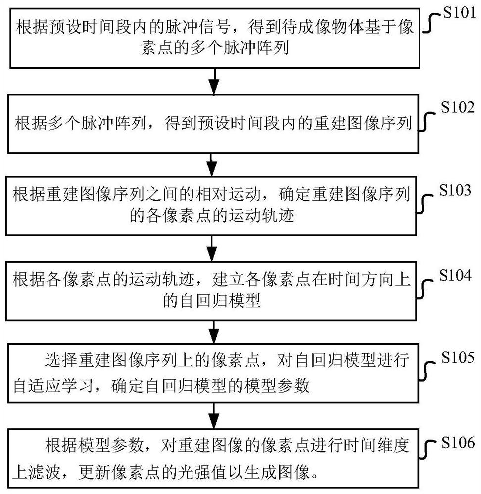
[0051] figure 1 A schematic diagram of the steps of the weight-based electric control movement method according to the embodiment of the present application is shown in .

[0052] Such as figure 1 As shown, the pulse signal-based adaptive imaging method of the embodiment of the present application specifically includes the following steps:

[0053] S101: Obtain multiple pixel-based pulse arrays of an object to be imaged according to pulse signals within a preset time period.

[0054] S102: Obtain a reconstructed image sequence within a preset time period according to the plurality of pulse arrays.

[0055] Wherein, according to the multiple pulse arrays, obtaining the reconstructed image sequence within a preset time period specifically includes: reconstructing the reconstructed image sequence by using a pulse interval algorithm.

[0056] S103: Determine the motion track of each pixel in the reconstructed image sequence according to the relative motion between the reconstru...

Embodiment 2

[0094] This embodiment provides an adaptive imaging system based on pulse signals. For details not disclosed in the adaptive imaging system based on pulse signals in this embodiment, please refer to the adaptive imaging methods based on pulse signals in other embodiments specific implementation content.

[0095] Figure 5 A schematic structural diagram of an adaptive imaging system based on a pulse signal according to an embodiment of the present application is shown in .

[0096] Such as Figure 5 As shown, the pulse signal-based adaptive imaging system of the embodiment of the present application specifically includes a pulse unit 10, an image reconstruction unit 20, a motion trajectory unit 30, an autoregressive model unit 40, a model parameter calculation unit 50, and an adaptive imaging unit 60 .

[0097] The pulse unit 10 is configured to obtain multiple pixel-based pulse arrays of the object to be imaged according to the pulse signal within a preset time period;

[...

Embodiment 3

[0119] This embodiment provides an adaptive imaging device based on a pulse signal. For details not disclosed in the adaptive imaging device based on a pulse signal in this embodiment, please refer to the adaptive imaging method based on a pulse signal in other embodiments Or the specific implementation content of the system.

[0120] Figure 6 A schematic structural diagram of an adaptive imaging device 400 based on a pulse signal according to an embodiment of the present application is shown in .

[0121] Such as Figure 6 As shown, the adaptive imaging device 400 includes:

[0122] Memory 402: for storing executable instructions; and

[0123] Processor 401: used to connect with memory 402 to execute executable instructions so as to complete the pulse signal-based adaptive imaging method.

[0124] Those skilled in the art can understand that the Figure 6 It is only an example of the adaptive imaging device 400, and does not constitute a limitation to the adaptive imagi...


PUM


Abstract

The embodiment of the present application provides a pulse signal-based adaptive imaging method, system, and computer medium. According to the pulse signal within a preset time period, multiple pulse arrays based on pixels of the object to be imaged are obtained; Array, to obtain the reconstructed image sequence within the preset time period; according to the relative motion between the reconstructed image sequences, determine the motion trajectory of each pixel in the reconstructed image sequence; according to the motion trajectory of each pixel, establish the time direction of each pixel The autoregressive model; adaptively select the pixels on the reconstructed image sequence, adaptively learn the autoregressive model, and determine the model parameters of the autoregressive model; according to the model parameters, filter the pixels of the reconstructed image sequence in the time dimension, Update the light intensity value of the pixel to generate the image. It solves the problem that traditional cameras are difficult to clearly image high-speed moving scene objects, and can produce images with high signal-to-noise ratio and no blur.

Description

technical field [0001] The present application belongs to the technical field of laser imaging, and in particular relates to an adaptive imaging method, system and computer medium based on pulse signals. Background technique [0002] With the development and progress of science and technology, traditional digital cameras usually shoot and image at a fixed frame rate, and each frame of image is generated in the following way: within a certain exposure time window, each pixel of the image sensor performs photoelectric conversion and Accumulated, the total amount of illumination of the pixel is obtained through analog-to-digital conversion after exposure. Because the information in the exposure time window is superimposed and recorded, this method cannot effectively image high-speed objects, which often leads to blurred imaging of high-speed moving objects. In recent years, the neural connection structure of the fovea of ​​the biological retina and the integral firing model of...

Claims


Application Information

Patent Timeline
Patent Type & Authority Patents(China)
IPC IPC(8): G06T11/00G06T5/00G06T5/10G06T7/20
CPCG06T11/00G06T5/003G06T5/10G06T7/20G06T2207/20004G06T2207/20024
Inventor 熊瑞勤赵菁黄铁军
Owner SPIKE VISION (BEIJING) TECHNOLOGY CO LTD
Why Eureka
Try Eureka