Sintering method of harmful dust and sludge in iron and steel plant

A sintering method and technology of iron and steel plants, applied in the field of sintering, can solve the problems affecting the sintering index and metallurgical properties, and achieve the effect of strong operability and simple process

Active Publication Date: 2021-06-29
SHANDONG IRON & STEEL CO LTD
View PDF3 Cites 1 Cited by
  • Summary
  • Abstract
  • Description
  • Claims
  • Application Information

AI Technical Summary

Problems solved by technology

[0005] The present invention solves the problem that dust and dust mud in the existing iron and steel plant are mixed in the sintering mixture, which affects the sintering index and metallurgical performance, and the cycle enrichment of harmful elements such as alkali metal K, Na and Zn has an important adverse effect on ironmaking problem, to provide a sintering method of harmful dust sludge in iron and steel plants

Method used


Image

  • Sintering method of harmful dust and sludge in iron and steel plant
  • Sintering method of harmful dust and sludge in iron and steel plant
  • Sintering method of harmful dust and sludge in iron and steel plant

Examples


Embodiment 1

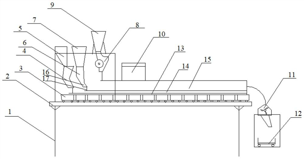
[0040] as attached figure 2 The above is a schematic structural view of a sintering machine according to an embodiment of the present invention. A sintering lane 2 is provided on the frame 1 of the sintering machine, and a sintering trolley 3 is arranged on the sintering lane 2. The sintering trolley 3 includes a trolley body and It is arranged on the material blocking plates on both sides of the trolley body.

[0041] On the sintering driveway 2, from the head to the tail, the material spreading mechanism I4, the dust ball spreading mechanism II6, the sintering raw material distributor 8 and the igniter 10, as well as the sintering ventilation system and the unloading device are arranged in sequence. There are crushers 11 and conveyors 12 below. The upper end of the discharge port of the dust ball spreading mechanism II6 is connected to the dust ball bin 7, the upper end of the dust ball spreading mechanism I4 is connected to the bottom bunker 5, and the top of the sinterin...

Embodiment 2

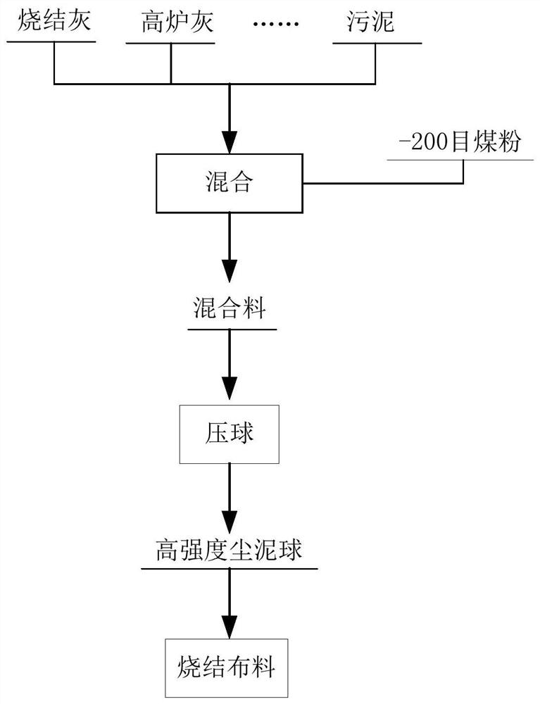
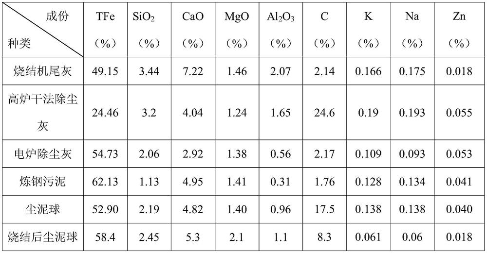
[0056] A sintering method for harmful dust sludge in iron and steel works, the method utilizes the sintering machine described in embodiment 1, and the dust sludge mixture in iron and steel enterprises includes shaft furnace dedusting ash, blast furnace dry dedusting ash, steelmaking coarse ash, and dedusting under the upper and lower troughs The composition of ash and steelmaking sludge is shown in Table 3 below.

[0057] Shaft furnace dedusting ash, blast furnace dry dedusting ash, steelmaking coarse ash, upper and lower trough dedusting ash, and steelmaking sludge are mixed at a ratio of 0.3:0.15:0.1:0.25:0.2 on a dry basis, respectively. Among them, Fe is all Fe 2 o 3 In terms of existing forms, K, Na, and Zn are represented by K 2 O, Na 2 O, ZnO meter. Coal powder is added according to the content of oxygen in the oxides of C and TFe, K, Na and Zn in the dust-sludge mixture to obtain a dust-slag mixture. The amount of pulverized coal added is to control the molar rat...


PUM

PropertyMeasurementUnit
particle sizeaaaaaaaaaa
thicknessaaaaaaaaaa

Abstract

The invention discloses a sintering method of harmful dust and sludge in an iron and steel plant. The sintering method comprises the following steps of: (1) mixing various dust and sludge in the iron and steel plant to obtain a dust and sludge mixture, and adding coal powder according to the contents of TFe, K, Na, Zn and C elements in the dust and sludge mixture to obtain a dust and sludge uniform mixture; (2) carrying out double-roller ball pressing on the dust and sludge uniform mixture obtained in the step (1) to obtain dust and sludge balls; and (3) sequentially distributing a bedding material, the dust and sludge balls obtained in the step (2) and a sintering raw material on a sintering trolley, and igniting and sintering. According to the sintering method, the harmful dust and sludge in the iron and steel plant are collected, after reasonable carbon distribution and full mixing are carried out, double-roller high-pressure ball pressing is carried out to obtain the high-strength dust and sludge balls, and then the bedding material, the high-strength dust and sludge balls and the sintering raw material are sequentially distributed into the sintering trolley for ignition and sintering.

Description

technical field [0001] The invention relates to the technical field of sintering, in particular to a sintering method of harmful dust sludge in iron and steel plants. Background technique [0002] Sinter is the main iron-containing raw material in the ironmaking process of iron and steel enterprises, accounting for about 70%. The sintering process not only produces sintered ore for ironmaking, but also handles various wastes such as iron-containing dust and sludge in iron and steel enterprises. At present, most of the dust and sludge from various iron and steel plants are recycled to the sintering raw material field, where they are mixed with sintering ore powder to form a sintering mixture, and then added flux and fuel for sintering. [0003] For example, Chinese patent document CN102492833A (201110383871.2) provides a method for applying iron-containing dust sludge to sintering. 45% to 50% iron-containing dust sludge, 17% to 22% iron concentrate, 0.6% to 0.8% slaked lime,...

Claims


Application Information

Patent Timeline
Patent Type & Authority Applications(China)
IPC IPC(8): C22B1/16C22B1/248
CPCC22B1/16C22B1/2406C22B1/248
Inventor 周小辉周林任军罗茂春张英付强刘德峰
Owner SHANDONG IRON & STEEL CO LTD
Why Eureka
Try Eureka