Spiral flow high-lift constant pressure pump body
A high-lift, constant-pressure pump technology, used in radial flow pumps, components of pumping devices for elastic fluids, pumps, etc. Instability, mechanical seal wear and other problems, to achieve the pump water path specification, ensure the service life, reduce the effect of resistance
- Summary
- Abstract
- Description
- Claims
- Application Information
AI Technical Summary
Problems solved by technology
Method used
Image
Examples
Embodiment 1
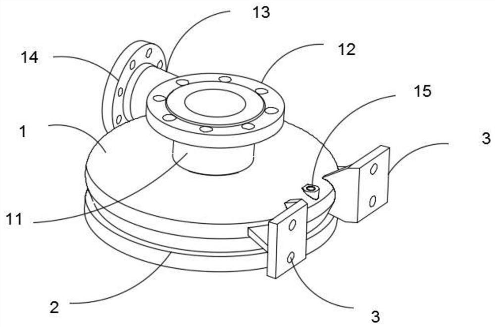
[0061] Such as figure 1 The spiral stream shown is high in a constant pressure pump pump body, mainly including: the upper casing 1 having a circular cross section, a lower casing 2 connected to the upper housing 1;
[0062] Such as Figure 4 As shown, the upper housing 1 and the lower casing 2 are connected by a fixed staple 4;
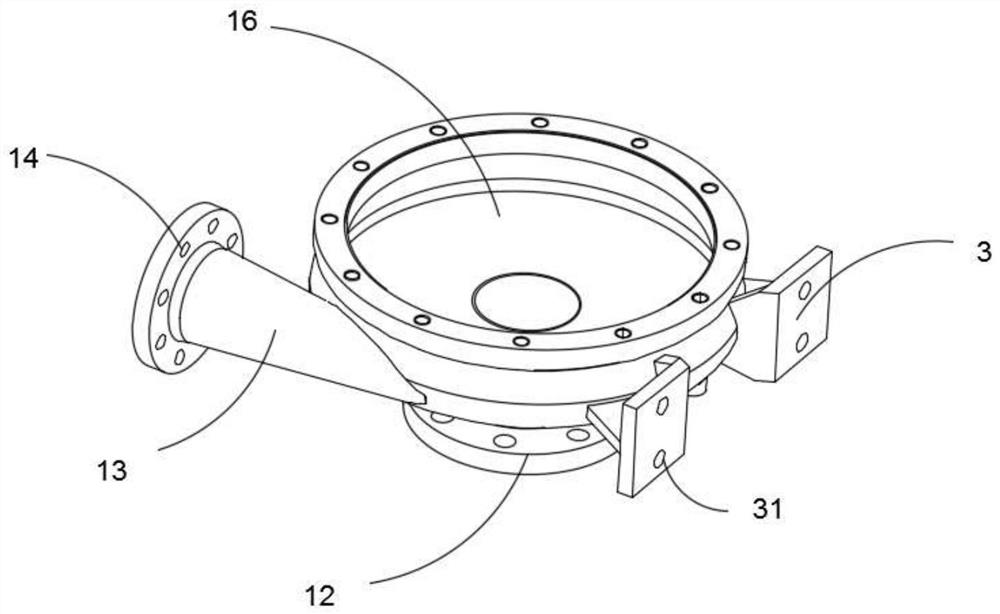
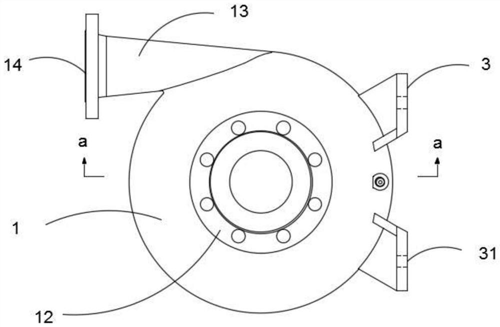
[0063] Such as figure 1 with Figure 4 As shown, the upper housing 1 includes: an effluent pipe 11 disposed at the upper housing 1 in the upper housing 1, provided in the upper housing 1 side for inlet pipe 13 The cavity 16 is provided inside the upper housing 1 for the water body 16;
[0064] Such as Figure 4 As shown, the cavity 16 includes a smooth cavity wall 161, an arc surface guide groove 162 disposed at the top of the cavity wall 161;
[0065] Such as Figure 4 As shown, the arc surface guide groove 162 has two, and the symmetrical is located on both sides of the outlet pipe 11;
[0066] Such as figure 1 As shown, a fixing plate 3 is provided on one...
Embodiment 2
[0082] Embodiment 2 and Example 1 differ in:
[0083] Such as Figure 11 As shown, the third slide 56 and the second slide 53 are connected between a curved fourth slide 8.
Embodiment 3
[0085] Embodiment 3 and Example 2 differ in:
[0086] Such as Figure 4 As shown, the bottom portion of the lower casing 2 is provided with a sound absorbing plate 21, the suction plate 21, built into a plurality of suction holes.
[0087] Such as Figure 4 Design, a plurality of shock absorbing spring 221 are coupled between the sound absorbing plate 21 and the suction plate 21 and the suction plate 21.
[0088] The second slide 53, the third slide 56, and the fourth slide 8 are limit slides, the drive chain 7, each sliding once, a distance of a third slider 71.
[0089] The method of use of the present invention is:
[0090] First, the upper housing 1 and the lower casing 2 are mounted by the fixing staple 21, and the suction plate 21 and the damper plate 22 are mounted, and the water pipe connecting member 12 is connected to the spray tube, and the water body is connected by the water pipe connection 14. Or adaptive pumping pipe, water tank;
[0091] Second, the electric stretch ...
PUM
 Abstract
Description
Claims
Application Information
 - R&D
- Intellectual Property
- Life Sciences
- Materials
- Tech Scout
- Unparalleled Data Quality
- Higher Quality Content
- 60% Fewer Hallucinations
Browse by: Latest US Patents, China's latest patents, Technical Efficacy Thesaurus, Application Domain, Technology Topic, Popular Technical Reports.
© 2025 PatSnap. All rights reserved.Legal|Privacy policy|Modern Slavery Act Transparency Statement|Sitemap|About US| Contact US: help@patsnap.com


