Multi-layer mesh moving bed waste gas purification system

An exhaust gas purification system and moving bed technology, applied in gas treatment, chemical instruments and methods, and separation of dispersed particles, can solve problems such as increased carbon emissions, short life cycle, and secondary pollution

Pending Publication Date: 2021-07-06
孙绍堂
View PDF0 Cites 1 Cited by
  • Summary
  • Abstract
  • Description
  • Claims
  • Application Information

AI Technical Summary

Problems solved by technology

[0003] At present, the fixed adsorption bed technology is basically used in the VOC organic waste gas treatment application market. No matter the process route chooses activated carbon, carbon fiber, adsorption resin, zeolite molecular sieve or honeycomb adsorption wheel, etc., its basic form is a fixed bed structure. The disadvantages of fixed adsorption beds gradually appear during long-term use, which affect the promotion and development of VOC organic waste gas treatment process with fixed bed structure
The fixed bed adsorption technology has the following defects: 1) The adsorption efficiency decreases with the increase of the use time, and the life cycle is short; 2) The regeneration efficiency of the regeneration technology is low, and there are potential safety hazards; 3) The waste activated carbon and other adsorption fillers have secondary pollution Problem; 4) Poor resistance to shock load variability, unstable adsorption efficiency of fixed bed, and unstable up-to-standard discharge;
[0004] 5) Most of the post-treatment processes are different forms of thermal oxidation treatment, which increases carbon emissions

Method used


Image

  • Multi-layer mesh moving bed waste gas purification system
  • Multi-layer mesh moving bed waste gas purification system
  • Multi-layer mesh moving bed waste gas purification system

Examples


Embodiment Construction

[0040] The embodiments of the present invention will be further described in detail below in conjunction with the drawings and embodiments. It should be understood that the specific embodiments described here are only used to explain the embodiments of the present invention, rather than to limit the embodiments of the present invention. In addition, it should be noted that, for the convenience of description, the drawings only show some but not all structures related to the embodiments of the present invention.

[0041] This proposal proposes a multi-layer mesh moving bed exhaust gas purification system, which is described in detail as follows.

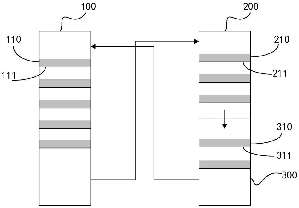
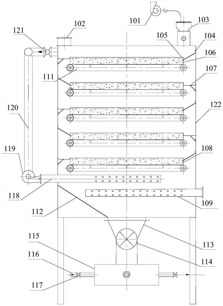
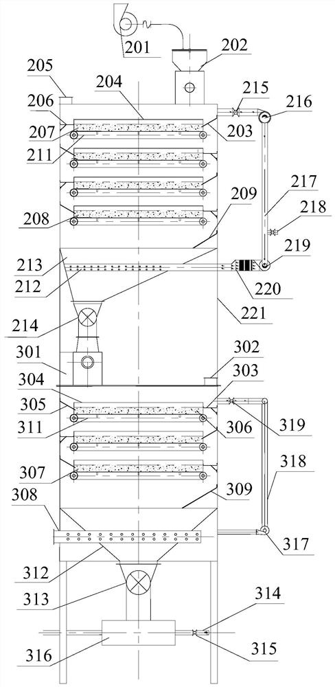
[0042] figure 1 A schematic block diagram of the structure of a multi-layer mesh moving bed exhaust gas purification system provided in an embodiment of the present invention, as shown in figure 1 As shown, the multi-layer mesh moving bed exhaust gas purification system includes an adsorption purification unit 100 , a desorption reg...


PUM


Abstract

The embodiment of the invention discloses a multi-layer mesh moving bed waste gas adsorption and purification system which comprises an adsorption and purification unit, a desorption and regeneration unit and a cooling unit, the adsorption and purification unit is used for uniformly discharging filler of an upper-stage adsorption layer to a lower-stage adsorption layer through a first conveying belt, feeding the saturated filler of the bottom adsorption layer into the desorption regeneration unit, and purifying organic waste gas flowing from bottom to top through each stage of adsorption layer; the desorption regeneration unit is used for uniformly discharging the filler of the upper-stage desorption layer to the lower-stage desorption layer through a second conveyor belt, feeding the filler of the bottom-stage desorption layer after high-temperature regeneration into the cooling unit, and heating the filler of each stage of desorption layer through hot nitrogen or water vapor flowing from bottom to top; and the cooling unit is used for uniformly discharging the filler of the upper-stage cooling layer to the lower-stage cooling layer through a third conveying belt, feeding the normal-temperature regenerated filler of the bottom-stage cooling layer into the adsorption purification unit, and cooling the filler of each stage of cooling layer through air flowing from bottom to top.

Description

technical field [0001] The embodiment of the present application relates to the technical field of air treatment, in particular to a multi-layer mesh moving bed waste gas purification system. Background technique [0002] Production workshops (such as: gluing and bonding workshops in shoe factories, printing workshops in printing factories, paint and coating production workshops, various organic chemical products production workshops, fiberglass product production workshops, painting, spraying workshops, musical instruments, wooden furniture surface treatment workshops Adhesive tapes, leather, adhesive production workshops, etc.) will produce many harmful gases during the manufacturing process of products, such as a variety of common VOC organic waste gases. The quality of indoor air quality and the emission of exhaust gases have become the current research one of the important subjects. [0003] At present, the fixed adsorption bed technology is basically used in the VOC o...

Claims


Application Information

Patent Timeline
Patent Type & Authority Applications(China)
IPC IPC(8): B01D53/08
CPCB01D53/08B01D2257/708B01D2259/4009
Inventor 孙绍堂
Owner 孙绍堂
Why Eureka
Try Eureka