Fine rubber powder production line

A production line and rubber powder technology, applied in the directions of magnetic separation, solid separation, smoke removal, etc., can solve the problems of unreasonable layout of fine rubber powder production line, high power consumption, unreasonable structure of collection cover, etc.

Pending Publication Date: 2021-07-06
JIANGSU ZHONGHONG ENVIRONMENT TECH CO LTD
View PDF15 Cites 0 Cited by
  • Summary
  • Abstract
  • Description
  • Claims
  • Application Information

AI Technical Summary

Problems solved by technology

[0003] Tire disintegration-cutting-rubbing-breaking-magnetic separation-sieving-grinding-collecting and packaging, many processes of the existing fine rubber powder production line are independent of each other and cannot be operated continuously; at the same time, the layout of the existing fine rubber powder production line is unreasonable (as before There is interference between the first process and the subsequent process); the dust collection cover in the gel breaking and magnetic separation process is not collected for the dust point, and the structure of the collection cover is unreasonable, which makes it inconvenient to maintain the equipment; in the gel breaking process, the added calcium powder bin exists. The problem of arching and quantitative transportation; in the grinding process, there is a problem of high power consumption

Method used


Image

  • Fine rubber powder production line
  • Fine rubber powder production line
  • Fine rubber powder production line

Examples


Embodiment Construction

[0073] The specific implementation manners of the present invention will be further described below in conjunction with the drawings and examples. The following examples are only used to illustrate the technical solution of the present invention more clearly, but not to limit the protection scope of the present invention.

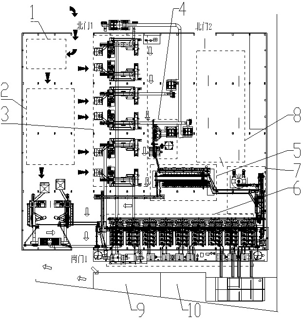
[0074] see figure 1 , the present invention relates to a fine rubber powder production line, comprising a block making area 1, a stacking area 2, a gel breaking area 3, a magnetic separation area 4, a screening area 5, a grinding area 6, a collection area 7, a fine rubber powder finished product area 8, a wool Silk stacking area 9 and collar stacking area 10;

[0075] ①. Tires are disassembled in Blocking Area 1; waste tires are sent to Blocking Area 1 through the first north gate;

[0076] Blocking area 1 includes a bead cutting machine (not shown in the figure);

[0077] After selecting hard materials such as steel nails, stones, and tiles, the waste t...


PUM


Abstract

The invention relates to a fine rubber powder production line. A tire is decomposed into a tire top, tire sides and opening rings in a block decomposing area; the tire top and the tire sides are cut into blocks in the block decomposing area and then fed into a rubber breaking area; rubber blocks are broken into rubber powder and steel wires in the rubber breaking area, and the rubber powder and the steel wires meeting the mesh number enter a magnetic separation area; steel wires in the rubber powder are separated and collected through a magnetic separation unit in the magnetic separation area, and the rubber powder is conveyed to a rubber powder bin; the rubber powder subjected to magnetic separation is fed into a closed screening machine for screening, the rubber powder meeting the mesh number is sent into a collecting area by blowing, and the rubber powder not meeting the specification is sent into a grinding area for grinding; in the grinding area, the rubber material passes through a material distributing spiral and then enters a pulverizer to be ground into rubber powder with a smaller particle size, the rubber powder meeting the required mesh number is conveyed to a collector to be packaged, and the rubber powder not meeting the mesh number requirement is conveyed back to the pulverizer to be crushed again; and finally, packaging is performed in a collecting area, and transportation is performed in a fine rubber powder finished product area. According to the fine rubber powder production line, from the waste tires to the fine rubber powder, multiple procedures are high in collaboration and do not interfere with one another, the production efficiency is high, and the production cost is low.

Description

technical field [0001] The invention relates to a fine rubber powder production line. It belongs to the technical field of mechanical equipment. Background technique [0002] Fine rubber powder production process includes: [0003] Tire disintegration-cutting-rubbing-breaking-magnetic separation-sieving-grinding-collecting and packaging, many processes of the existing fine rubber powder production line are independent of each other and cannot be operated continuously; at the same time, the layout of the existing fine rubber powder production line is unreasonable (as before There is interference between the first process and the subsequent process); the dust collection cover in the gel breaking and magnetic separation process is not collected for the dust point, and the structure of the collection cover is unreasonable, which makes it inconvenient to maintain the equipment; in the gel breaking process, the added calcium powder bin exists. The problem of arching and quantita...

Claims


Application Information

Patent Timeline
IPC IPC(8): B02C21/00B02C23/02B02C23/14B02C23/00B08B15/02B03C1/30B04C9/00
CPCB02C21/00B02C23/02B02C23/14B02C23/00B08B15/02B03C1/30B04C9/00B02C2201/04
Inventor 许麒俞麟张满刚蒋磊徐力黄泽尔兰桂勇杨世芹
Owner JIANGSU ZHONGHONG ENVIRONMENT TECH CO LTD
Why Eureka
Try Eureka