Drum screen mesh unblocking device and drum screen mesh unblocking method

A drum sieve and drum technology, applied in chemical instruments and methods, sieves, solid separation, etc., can solve problems such as inability to effectively identify drum sieve holes, unsuitability, etc.

Active Publication Date: 2021-07-06
NANJING UNIV
View PDF8 Cites 5 Cited by
  • Summary
  • Abstract
  • Description
  • Claims
  • Application Information

AI Technical Summary

Problems solved by technology

However, this method is only suitable for monitoring flat sieves, and the drum sieve for screening garbage is cylindrical, and this method is not suitable
In addition, the color of garbage is changeable and uncertain, so image monitoring and grayscale recognition methods cannot effectively identify the screen holes on the drum sieve

Method used


Image

  • Drum screen mesh unblocking device and drum screen mesh unblocking method
  • Drum screen mesh unblocking device and drum screen mesh unblocking method

Examples


Embodiment 1

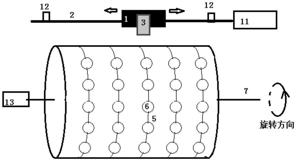
[0026] Such as Figure 1-2 As shown, the trommel screen hole unclogging device includes a stepping system, a laser distance measuring system, an angle encoding system, a unclogging system and a control system;

[0027] The stepping system includes a slide rail 2, a slider 1, a stepping motor 11 and a limit sensor 12. The slide rail is parallel to the rotation axis of the trommel screen, and the stepping motor drives the slider to reciprocate on the slide rail , the two ends of the slide rail are provided with limit sensors, the laser ranging system 3 and the gas nozzle 4 of the blockage removal system are fixed on both sides of the slider, facing the drum surface of the trommel 5, and moving with the slider;

[0028] The laser ranging system includes a laser emitting and receiving probe, a data analysis unit and a data transmission unit. The laser emitting and receiving probe emits and receives laser signals, and records the time difference between the emitted and received las...

Embodiment 2

[0034] A method for unclogging a trommel sieve hole, the steps comprising:

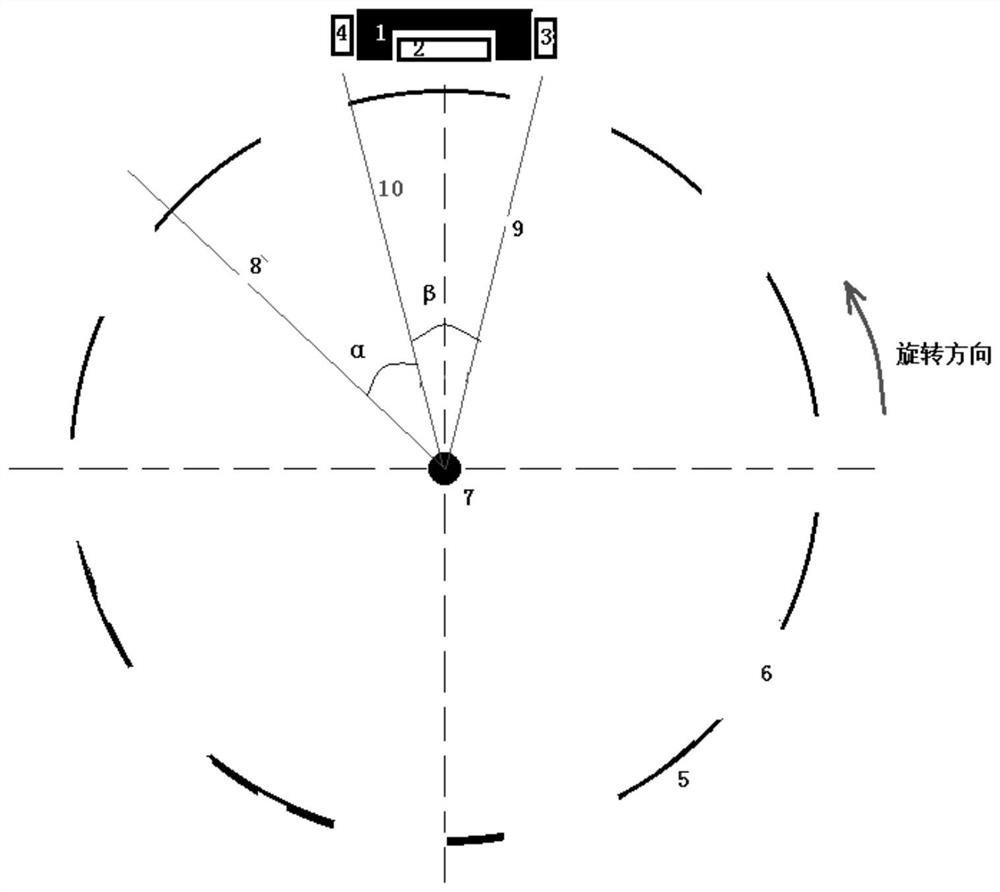
[0035] (1) The slider dragged by the stepping motor carries the laser ranging system and the gas nozzle, moves on the outside of the drum in a direction parallel to the rotation axis of the drum, and moves to a certain section position (m) of the drum screen to stop, the slider The beam emitted by the connected laser probe irradiates the surface of the roller at this position, that is, the surface of the roller at this position is measured; the roller rotates once, and the laser scans the surface of the roller at this section position for one circle;

[0036](2) After the slider stops, the laser ranging system connected to the slider measures the distance to the surface of the drum, and the angle encoder reads the angle at the same time. At this moment, the position of the light spot cast by the laser emitting and receiving probe on the drum wall is determined The position data (m) of the section wher...


PUM


Abstract

The invention further discloses a drum screen mesh unblocking device. A stepping motor drives a sliding block to move on a sliding rail in a reciprocating mode, and a laser ranging system and a gas nozzle of an unblocking system are fixed to the two sides of the sliding block, right face the drum curved surface of the drum screen and move along with the sliding block. the laser ranging system measures the laser irradiation distance, an angle encoding system determines the rotating angle of the drum around a rotating shaft relative to the 0 position, a control system judges whether the screen meshes are blocked or not, and a gas spray head of the unblocking system is used for flushing the blocked screen meshes. The invention further discloses a drum screen mesh unblocking method. The device and a drum screen system work synchronously, the drum is not required to rotate at a constant speed, each screen mesh can be scanned, the state of the screen meshes can be automatically detected, and unblocking operation can be automatically carried out; and positioning, distance measurement, recognition and unblocking are conducted in a reciprocating mode, it is guaranteed that the drum screen equipment is not stopped in the using process, and therefore the equipment using efficiency is improved, and the labor intensity of workers is reduced.

Description

technical field [0001] The invention relates to a device for removing clogging of a drum screen hole and a method for removing clogging of a drum screen hole. Background technique [0002] Mixed waste contains soil and other particles, which can be separated and reused. On the garbage sorting line, the mixed garbage passes through a large drum sieve to screen out the soil, and the remaining materials (garbage) enter the next link. During the operation of the trommel screen, the phenomenon that the screen hole may be blocked by the material may affect the work efficiency. In the past, after the equipment worked for 2 to 4 hours, it could only be shut down, and the blocked screen holes were dredged manually, which was time-consuming and laborious, and affected the efficiency of the assembly line. Some people add protrusions such as scrapers inside the drum screen, and randomly crush the dry sand during the rotation of the drum screen, so as to reduce the occurrence of clogge...

Claims


Application Information

Patent Timeline
Patent Type & Authority Applications(China)
IPC IPC(8): B07B1/22B07B1/42B07B1/55
CPCB07B1/22B07B1/42B07B1/55
Inventor 胡利群陈敦军
Owner NANJING UNIV
Why Eureka
Try Eureka