Lifting type dust-free wall surface grinding machine for decoration engineering
A lifting type, grinding machine technology, applied in the direction of machine tools, grinding racks, and grinding machine parts suitable for grinding workpiece planes, etc., can solve the problem of low grinding efficiency, inconvenient grinding disc replacement, inconvenient promotion and use And other issues
- Summary
- Abstract
- Description
- Claims
- Application Information
AI Technical Summary
Problems solved by technology
Method used
Image
Examples
Embodiment 1
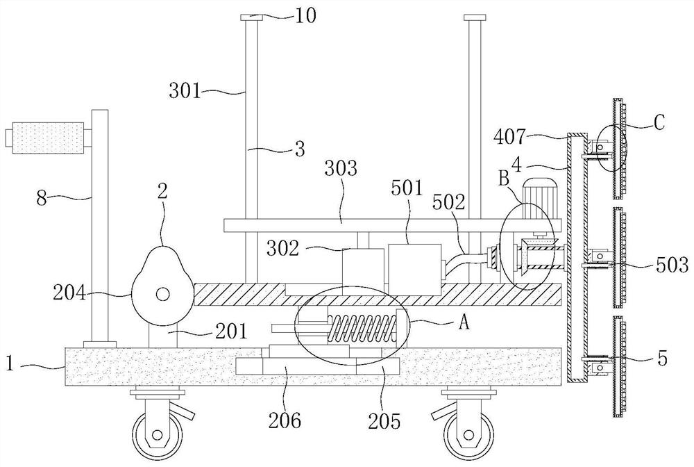
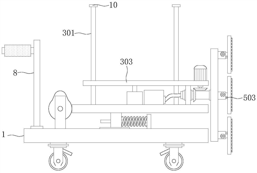
[0027] See Figure 1-7 The present invention provides a technical solution: a decorative engineering, a lifting-type dust-free wall grinding machine, including a working bottom plate 1, and an adjustment structure 2, a regulating mechanism 3, a grinding mechanism 4 and a dust removal mechanism 5 are provided above the working bottom plate 1. The top portion of the working bottom plate 1 is provided with a positioning plate 6, and the outer wall of the positioning plate 6 is provided with mounting rod 7, and the top of the working bottom plate 1 is fixedly mounted with push hands 8, and the outer wall sleeve of the pusher 8 is provided with a non-slip sleeve.
[0028] Further, the bottom activity of the working bottom plate 1 has four sets of walking wheels and rectangular distribution, and all of the four sets of walking wheel are provided with a brake, which is convenient for fixing the device while increasing the flexibility and stability of the device.
Embodiment 2
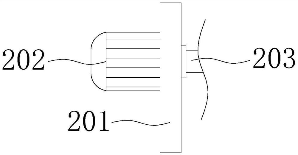
[0030] See Figure 1-7On the basis of the first example, the adjustment structure 2 includes a motor fixing plate 201, a first motor 202, a rotating rod 203, a cam 204, a slider 206, a connection block 207, a mounting cross plate 208, and a reset spring 209, a working bottom plate 1. The top is fixedly mounted with two sets of motor fixing plate 201, and the two sets of motor fixing plates 201 are set before and after, wherein the rear side of the one set of motor fixing plate 201 is fixedly mounted with a first motor 202, and the adjacent side of the two sets of motor fixing plates 201. The wall is transferred with the rotating rod 203, and the output shaft of the first motor 202 extends to the front side of one of the motor fixing plate 201 and fixed to the rotating rod 203, and the outer wall sleeve of the rotary rod 203 is provided with a cam 204. The top of the working bottom plate 1 opens the slide 205, the inside of the chute 205 is slidable, and the top portion of the slide...
PUM
 Abstract
Description
Claims
Application Information
 - R&D
- Intellectual Property
- Life Sciences
- Materials
- Tech Scout
- Unparalleled Data Quality
- Higher Quality Content
- 60% Fewer Hallucinations
Browse by: Latest US Patents, China's latest patents, Technical Efficacy Thesaurus, Application Domain, Technology Topic, Popular Technical Reports.
© 2025 PatSnap. All rights reserved.Legal|Privacy policy|Modern Slavery Act Transparency Statement|Sitemap|About US| Contact US: help@patsnap.com


