
Segmented construction method for gravity retaining wall

A construction method and retaining wall technology, applied in artificial islands, water conservancy projects, infrastructure projects, etc., can solve the problems of high construction joint construction requirements, decreased overall strength of retaining walls, difficulty in one-time forming and high risks

Inactive Publication Date: 2021-07-06
肖臣
View PDF7 Cites 2 Cited by
  • Summary
  • Abstract
  • Description
  • Claims
  • Application Information

AI Technical Summary

Problems solved by technology

[0005] Due to the height relationship, the existing retaining wall is difficult and risky to form at one time during construction, so it needs to be formed in sections. Generally, construction joints are reserved for pouring, but the construction requirements for construction joints are relatively high. Otherwise, it is easy to cause the overall strength of the retaining wall to decrease and cause instability, especially for water seepage. Once water seepage occurs in the construction joints, the strength of the connection will be significantly reduced after the internal erosion

Method used


Image

  • Segmented construction method for gravity retaining wall
  • Segmented construction method for gravity retaining wall
  • Segmented construction method for gravity retaining wall

Examples


Embodiment 1

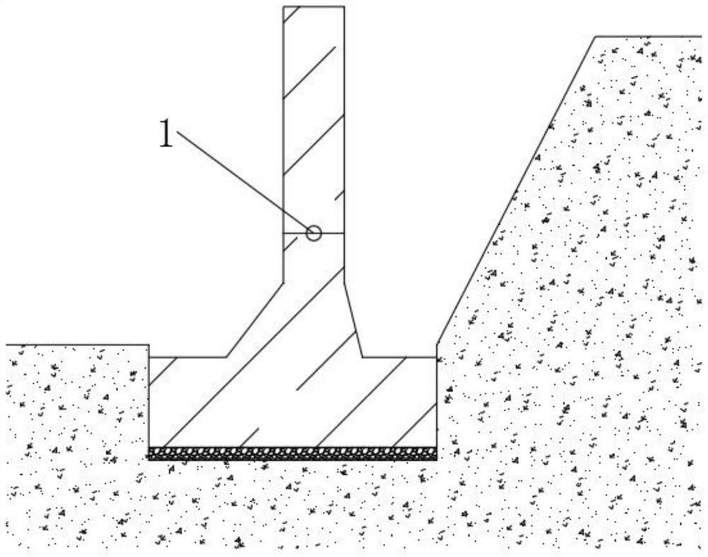
[0045] see figure 1 , a segmented construction method for a gravity retaining wall, comprising the following steps:

[0046] S1. Excavate the foundation pit, then clean up the garbage and sundries in the foundation pit, level and compact it, and then lay a 5cm gravel cushion;

[0047] S2. Set out line measurement to determine the coordinate points of the cap, including the plane coordinates and elevation of the corner points, and then erect the formwork and bind the steel bars, wherein the height of the formwork is 2cm higher than the height of the cap;

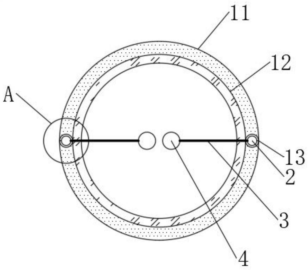
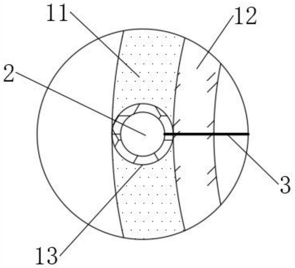
[0048] S3. Pour concrete into the formwork and vibrate evenly, and reserve a plurality of evenly distributed anti-seepage balls 1 at the construction joints. After 3 days, remove the formwork to cover the geotextile and sprinkle water for maintenance until the strength reaches 80% of the design value;

[0049] S4. Carry out chiseling treatment at the construction joints at the upper end of the cap, and clean up the debris, e...

Embodiment 2

[0062] A segmented construction method for a gravity retaining wall, comprising the following steps:

[0063] S1. Excavate the foundation pit, then clean up the garbage and sundries in the foundation pit, level and compact it, and then lay an 8cm gravel cushion;

[0064] S2. Set out the line measurement to determine the coordinate points of the cap, including the plane coordinates and elevation of the corner points, and then erect the formwork and bind the steel bars, wherein the height of the formwork is 2.5cm higher than the height of the cap;

[0065] S3. Pour concrete into the formwork and vibrate evenly, and reserve a plurality of evenly distributed anti-seepage balls 1 at the construction joints. After 5 days, remove the formwork to cover the geotextile and sprinkle water for maintenance until the strength reaches 80% of the design value;

[0066] S4. Carry out chiseling treatment at the construction joints at the upper end of the cap, and clean up the debris, erect the ...

Embodiment 3

[0074] A segmented construction method for a gravity retaining wall, comprising the following steps:

[0075] S1. Excavate the foundation pit, then clean up the garbage and sundries in the foundation pit, level and compact it, and then lay a 10cm gravel cushion;

[0076] S2. Set out line measurement to determine the coordinate points of the cap, including the plane coordinates and elevation of the corner points, and then erect the formwork and bind the steel bars, wherein the height of the formwork is 3cm higher than the height of the cap;

[0077] S3. Pour concrete into the formwork and vibrate evenly, and reserve a plurality of evenly distributed anti-seepage balls 1 at the construction joints. After 7 days, remove the formwork to cover the geotextile and sprinkle water for maintenance until the strength reaches 80% of the design value;

[0078] S4. Carry out roughing treatment at the construction joints at the upper end of the cap, and clean up the debris, erect the wall fo...


PUM

PropertyMeasurementUnit
heightaaaaaaaaaa

Abstract

The invention discloses a segmented construction method for a gravity retaining wall, and belongs to the technical field of building construction. According to the segmented construction method for the gravity retaining wall, a plurality of evenly-distributed anti-seepage balls can be pre-buried in a construction joint, and after a wall body is integrally formed, the caulking action of the anti-seepage balls is triggered through a magnetic field, the anti-seepage balls extend towards pores existing at the construction joint under the traction of magnetically-induced microspheres, after water permeates into the anti-seepage balls, the water is conveyed into the anti-seepage balls through a fiber pipe, a chemical reaction is triggered in a triggering ball to generate a large amount of gas, and magnetic plugging particles are migrated to the pores along with the gas under the guiding action of magnetic force. On one hand, continuously permeating water is blown out, on the other hand, the magnetic plugging particles can obviously expand for plugging after absorbing the water, the air pressure is increased along with continuous generation of gas until an isolation spherical shell is burst, under the extrusion effect, a curing material is forced to migrate to the gap to trigger the curing action, so that high-strength permanent plugging is realized, effective anti-seepage can be achieved, and therefore, the construction quality of the retaining wall is indirectly improved.

Description

technical field [0001] The invention relates to the technical field of building construction, in particular to a segmented construction method of a gravity retaining wall. Background technique [0002] A retaining wall refers to a structure that supports roadbed fill or hillside soil and prevents the deformation and instability of fill or soil. [0003] In the cross section of the retaining wall, the part directly in contact with the supported soil is called the back of the wall; the part opposite to the back of the wall is called the wall; the part in direct contact with the foundation is called the base; The top surface of the wall is called the top of the wall; the front end of the base is called the toe of the wall; the rear end of the base is called the heel of the wall. [0004] The gravity retaining wall balances the soil mass by its own gravity. Generally, the type is simple, the construction is convenient, the amount of masonry is large, and the requirements for th...

Claims


Application Information

Patent Timeline
Patent Type & Authority Applications(China)
IPC IPC(8): E02D29/02E02D29/16E02D31/02C04B28/04C04B40/02
CPCE02D29/0275E02D29/16E02D31/02C04B28/04C04B40/0277E02D2300/002E02D2300/0009E02D2250/0023E02D2250/0007E02D2300/0079
Inventor 肖臣
Owner 肖臣
Learn More