Cooling sleeve and optical fiber conduit with same

A technology for cooling sleeves and optical fiber conduits, applied in the field of medical devices, can solve the problems affecting the stability and accuracy of laser light output, equipment collision and deformation, and increased manufacturing costs, and achieves good cooling effect, reduced volume, and smooth installation process. slippery effect

Pending Publication Date: 2021-07-09
HANGZHOU GENLIGHT MEDTECH CO LTD
View PDF0 Cites 3 Cited by
  • Summary
  • Abstract
  • Description
  • Claims
  • Application Information

AI Technical Summary

Problems solved by technology

However, in the existing optical fiber cooling system, the proximal end of the optical fiber is completely exposed in the internal circulation pipeline without support and fixed. When the flow rate of the cooling medium flowing into the internal circulation pipeline is high, the proximal end of the optical fiber will inevitably produce Shaking makes the optical fiber deviate from the axis of the cooling jacket, and even the light emitting part of the optical fiber is attached to the inner wall of the inner tube, which affects the stability and accuracy of the laser light output
Furthermore, the existing internal circulation pipeline and external circulation pipeline only rely on the fixed seat to fix a single position, which is very easy to cause collision deformation or wear of the equipment under the action of external force (for example, during equipment transportation), lead to an increase in manufacturing costs
In addition, the circulation pipeline through which the fluid flows in the existing cooling jacket is relatively single, and there may be a cross-flow phenomenon when the flow rate of the cooling medium is relatively gentle, thereby affecting the cooling effect

Method used


Image

  • Cooling sleeve and optical fiber conduit with same
  • Cooling sleeve and optical fiber conduit with same
  • Cooling sleeve and optical fiber conduit with same

Examples


Embodiment Construction

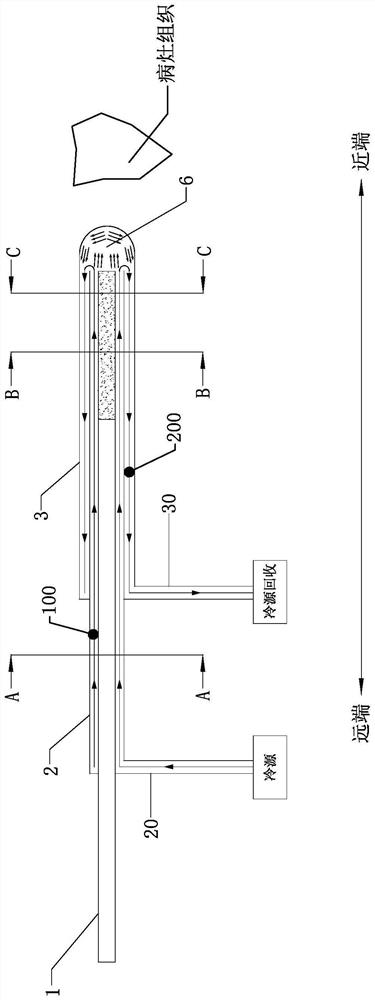
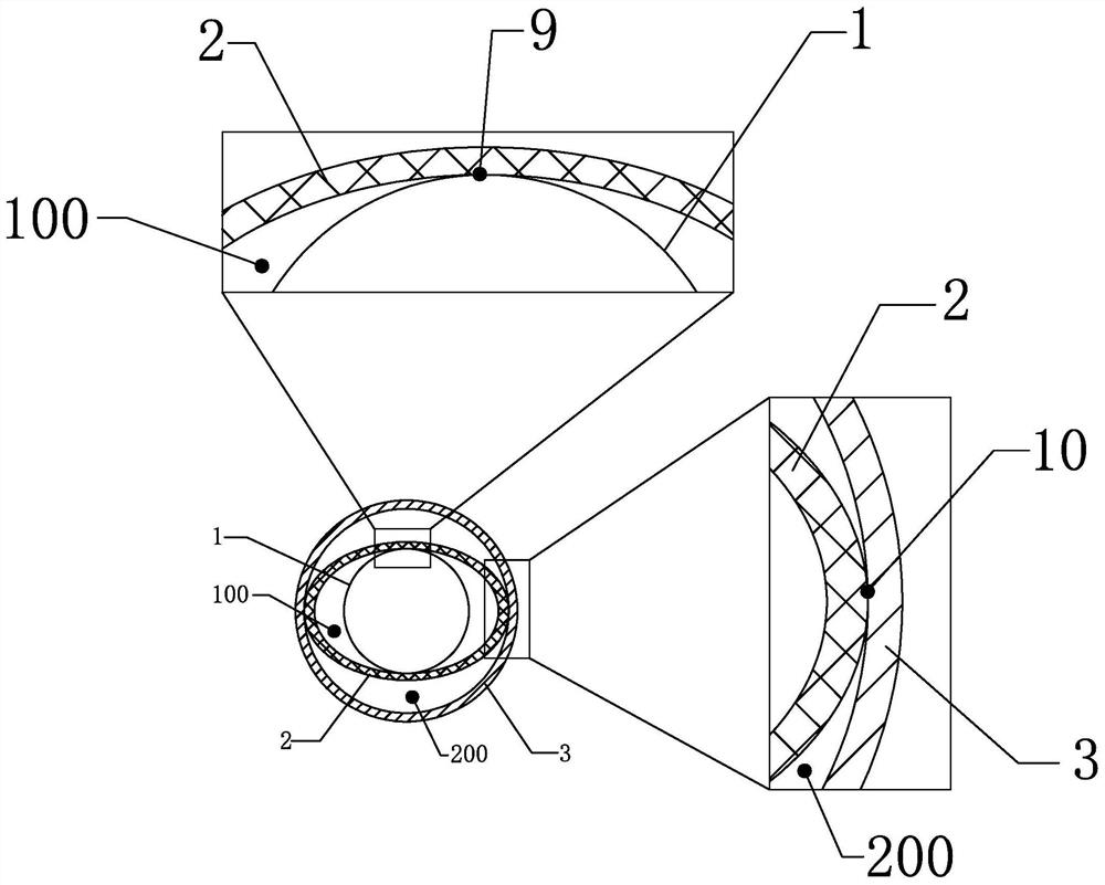
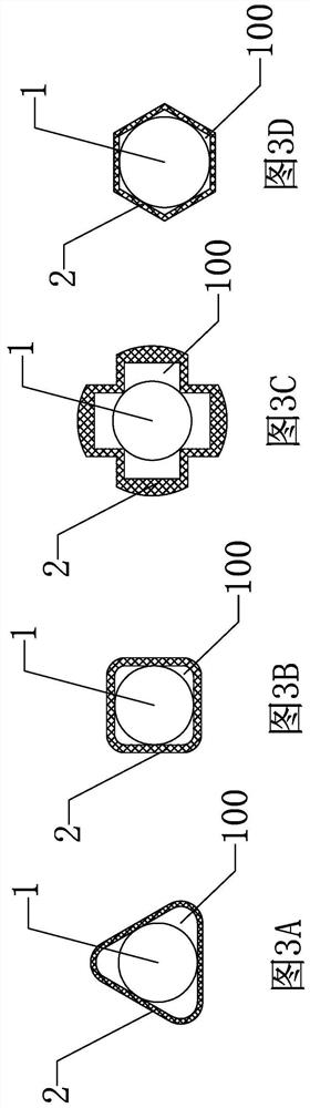
[0069] A cooling jacket proposed by the present invention, which sequentially includes a strip or tube to be cooled, an inner tube and an outer tube from the inside to the outside, the key lies in the strip or tube to be cooled, the inner tube The three are assembled and designed in a line contact or surface contact with the outer tube, or a mixed contact method of line contact and surface contact, and the coaxial self-support between the three can be realized without additional support structures; The multiple fluid cavities formed by this structure also avoid the cross-flow phenomenon of the fluid and ensure the cooling effect of the cooling jacket.

[0070] In the cooling jacket of the present invention, in magnetic resonance imaging-guided laser interstitial thermotherapy (LITT for short), the strip or tube to be cooled is an optical fiber. The following will take LITT technology as the creation background and describe the present invention in detail in conjunction with th...


PUM


Abstract

The invention provides a cooling sleeve which comprises an inner pipe, an optical fiber is arranged in the inner pipe, the outer wall of the optical fiber is in contact with the inner wall of the inner pipe to form a plurality of first contact parts extending in the axial direction, and axial gaps between the adjacent first contact parts form first circulation channels; the inner pipe is arranged in an outer pipe, the inner wall of the outer pipe makes contact with the outer wall of the inner pipe to form a plurality of second contact parts extending in the axial direction, and axial gaps between the adjacent second contact parts form second circulation channels; the near ends of the first circulation channels and the near ends of the second circulation channels are communicated at the near end of the outer pipe to form a back-flow cavity; and the far ends of the first circulation channels and the far ends of the second circulation channels are respectively and independently communicated with the outside. The invention further provides an optical fiber conduit with the cooling sleeve. The cooling sleeve and the optical fiber conduit with the same are ingenious in conception, and coaxial self-supporting among the inner pipe, the outer pipe and the optical fiber is achieved through the contact mode of the inner pipe, the outer pipe and the optical fiber.

Description

technical field [0001] The invention relates to the field of medical equipment, in particular to a cooling sleeve and an optical fiber guide with the cooling sleeve. Background technique [0002] Advances in modern cutting-edge science and technology have brought new developments in the diagnosis and treatment of intracranial tumors, and the survival expectations and survival rates of brain tumor patients have been greatly improved. Among them, laser interstitial hyperthermia (laser interstitial hyperthermia) guided by magnetic resonance imaging (MRI) thermal therapy, LITT) played a great role. The laser interstitial hyperthermia is a kind of percutaneous minimally invasive surgery under the guidance of stereotaxy. The laser acts on the target through the optical fiber to selectively ablate the diseased tissue. During the operation, the light energy is transmitted to the lesion tissue through the optical fiber for precise irradiation, and the light-to-heat conversion is rea...

Claims


Application Information

Patent Timeline
Patent Type & Authority Applications(China)
IPC IPC(8): A61B18/24
CPCA61B18/24A61B2018/00011A61B2018/00029A61B2018/00321A61B2018/00023A61B2018/00446A61B2018/00577A61B2018/2253A61B2018/00172
Inventor 金慧杰曹鹏夏良道陈新蕾廖响亮
Owner HANGZHOU GENLIGHT MEDTECH CO LTD
Why Eureka
Try Eureka