
Variable-flow solid-liquid mixing engine

A solid-liquid mixing and engine technology, which is applied in the direction of machines/engines, rocket engine devices, mechanical equipment, etc., can solve the problems of easy wear and low service life of needle cones, and achieve stable transportation, excellent pressure resistance, and reduced quality Effect

Active Publication Date: 2021-07-09
NORTHWESTERN POLYTECHNICAL UNIV +1
View PDF9 Cites 4 Cited by
  • Summary
  • Abstract
  • Description
  • Claims
  • Application Information

AI Technical Summary

Problems solved by technology

However, the needle cone of this device is easy to wear and needs to be disassembled and replaced frequently, and the service life is low

Method used


Image

  • Variable-flow solid-liquid mixing engine
  • Variable-flow solid-liquid mixing engine
  • Variable-flow solid-liquid mixing engine

Examples


example 1

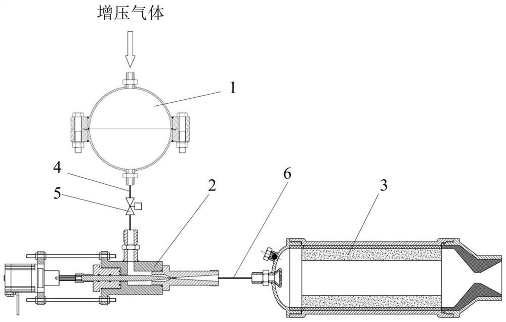
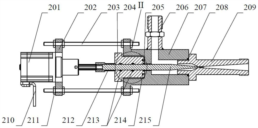
[0057] The fuel of the solid-liquid hybrid engine is paraffin wax, the drug type of the fuel is tube type, and it is loaded into the thrust chamber in the form of free filling. The oxidant is nitrous oxide, which is filled into the oxidant storage tank in advance, and the pressurized gas is nitrogen. The flow rate is adjusted by the movement of the cavitation venturi needle cone. The flow rate of the oxidant changes from small to large. It is divided into 3 stages. The flow rate of each stage is 30g / s, 50g / s and 80g / s respectively. The initial position of the needle cone is zero, and the positions corresponding to the needle cone are 0mm, 1mm and 2mm respectively. 17s.

[0058]After the assembly of the various components of the solid-liquid hybrid engine is completed, the control valve on the first pipeline is opened, and under the extrusion of the pressurized gas, the oxidant flows through the adjustable cavitation venturi tube to be restricted, and then reaches the thrust th...

example 2

[0060] The fuel of the solid-liquid hybrid engine is HTPB (hydroxyl-terminated polybutadiene). The fuel drug type is star-shaped, which is loaded into the thrust chamber in the form of free filling. The gas is nitrogen. The flow rate is adjusted by the movement of the cavitation venturi needle cone. The flow rate of the oxidant changes from large to small and then to large. It is divided into 3 stages, and the flow of each stage is 50g / s, 30g / s and 80g / s respectively. , it is stipulated that the initial position of the needle cone is the zero position, the corresponding positions of the needle cone are 0mm, -1mm and 1mm respectively, the supply time is 3s, the switching time of the working condition is 1s, and the flow rate changes from large to small. The speed of the needle cone is 1mm / s, the movement speed of the needle cone is 2mm / s when the flow rate changes from small to large, and it takes 11s to change the flow rate.

[0061] After the assembly of the various compone...


PUM

PropertyMeasurementUnit
Cone angleaaaaaaaaaa
Axial lengthaaaaaaaaaa

Abstract

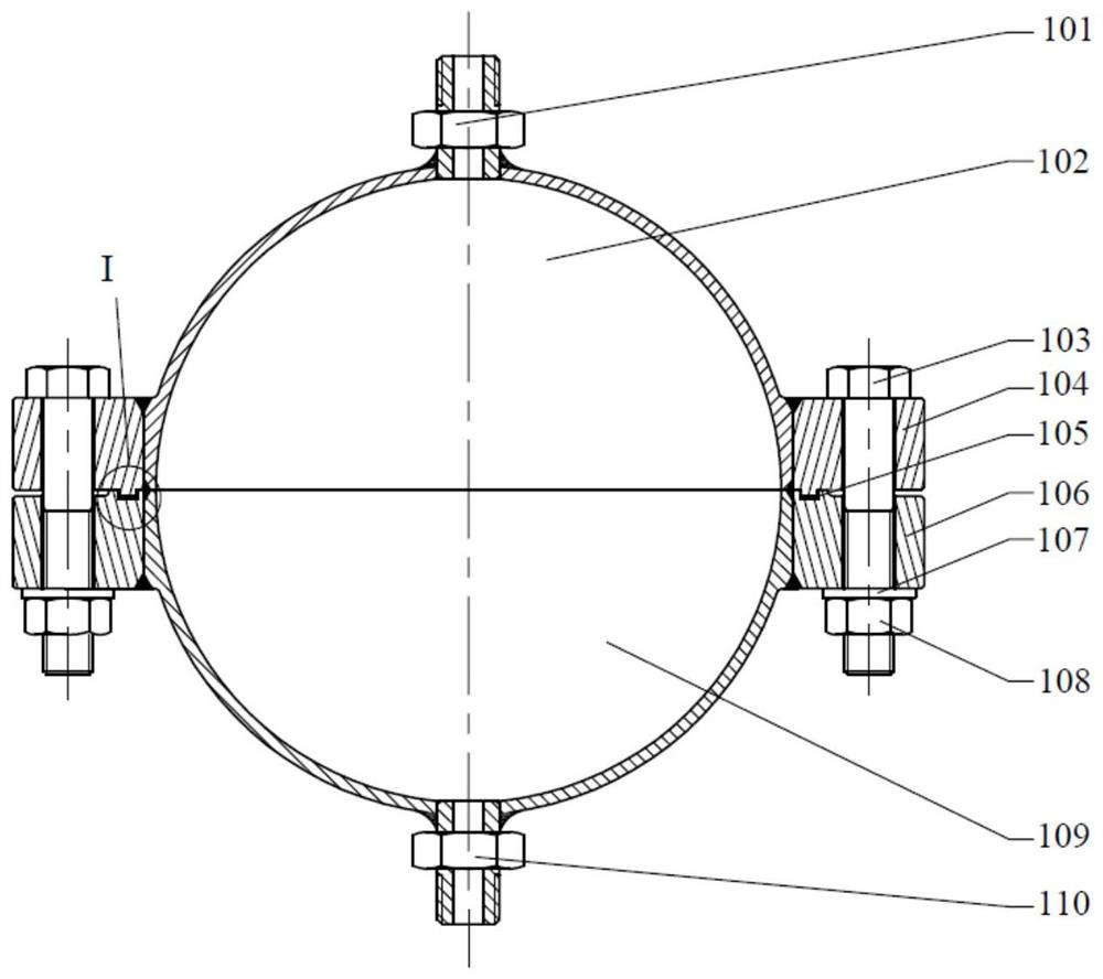
The invention discloses a variable-flow solid-liquid mixing engine, and belongs to the field of solid-liquid mixing engines. The variable-flow solid-liquid mixing engine comprises an oxidizing agent storage box, a thrust chamber, a control valve and an adjustable cavitation venturi tube, wherein the oxidizing agent storage box communicates with the thrust chamber through a pipeline and the adjustable cavitation venturi tube to input an oxidizing agent into the thrust chamber, the control valve installed on the pipeline controls on-off of the oxidizing agent, the adjustable cavitation venturi tube comprises a stepping motor, a fixed flange plate, a venturi tube pressing screw, a venturi tube inlet joint, an adjustable cavitation venturi tube shell, a cavitation venturi tube and a needle awl, the axial movement of the needle awl is controlled through the stepping motor, the gap between the needle awl and the throat diameter of the cavitation venturi tube is changed, and therefore, the flow of oxidizing agent supply is changed, and thrust adjustment is achieved. The adjustable cavitation venturi tube adopted by the variable-flow solid-liquid mixing engine can simply realize large-range flow regulation.

Description

technical field [0001] The invention belongs to the field of solid-liquid hybrid engines, in particular to a variable-flow solid-liquid hybrid engine. Background technique [0002] Rocket engines are the power systems of rockets, missiles and various spacecraft. With the development of the aerospace industry, the content and form of space missions have gradually increased, especially in the fields of spacecraft orbital maneuvering, space travel, and rendezvous and docking. The thrust adjustment capability of the engine puts forward higher requirements. Since long-term thrust adjustment is generally required in space missions, the engine reliability requirements are high; at the same time, limited by the overall design of the aircraft, the system installation space is often limited, which also puts forward the miniaturization requirements for the propulsion system. [0003] According to the different physical states of the propellant, rocket motors are often divided into sol...

Claims


Application Information

Patent Timeline
IPC IPC(8): F02K9/72F02K9/95F02K9/97
CPCF02K9/72F02K9/95F02K9/97
Inventor 刘林林季祯王亚东武冠杰陈泽斌刘喆李卓王占利
Owner NORTHWESTERN POLYTECHNICAL UNIV
Learn More