Long-life micro-column array graphite and metal composite cathode structure and preparation method thereof

A technology of microcolumn array and graphite cathode, which is applied in the field of composite cathode structure and preparation of long-life microcolumn array graphite and metal for maser, can solve the problem of losing stable electron beam emission, reducing beam coupling efficiency, losing Problems such as the raised launch structure can improve the ability to work stably for a long time, reduce the generation of plasma, and solve the effect of random changes in the launch position

Pending Publication Date: 2021-07-09
NORTHWEST INST OF NUCLEAR TECH
View PDF0 Cites 0 Cited by
  • Summary
  • Abstract
  • Description
  • Claims
  • Application Information

AI Technical Summary

Problems solved by technology

[0003] The purpose of the present invention is to solve the serious consumption of the convex emission structure in the existing microcolumn graphite cathode structure, or even completely lose the convex emission structure, thereby losing the effect of stabilizing the emission of electron beams, and the porous structure of the graphite material itself is bombarded by electron beams. Afterwards, it is easy to release gas, which leads to the technical problems of system vacuum degree decrease, beam wave coupling efficiency decrease and system device insulation decrease. Provide a composite cathode structure of long-life microcolumn array graphite and metal and its preparation method

Method used


Image

  • Long-life micro-column array graphite and metal composite cathode structure and preparation method thereof
  • Long-life micro-column array graphite and metal composite cathode structure and preparation method thereof
  • Long-life micro-column array graphite and metal composite cathode structure and preparation method thereof

Examples


Embodiment 1

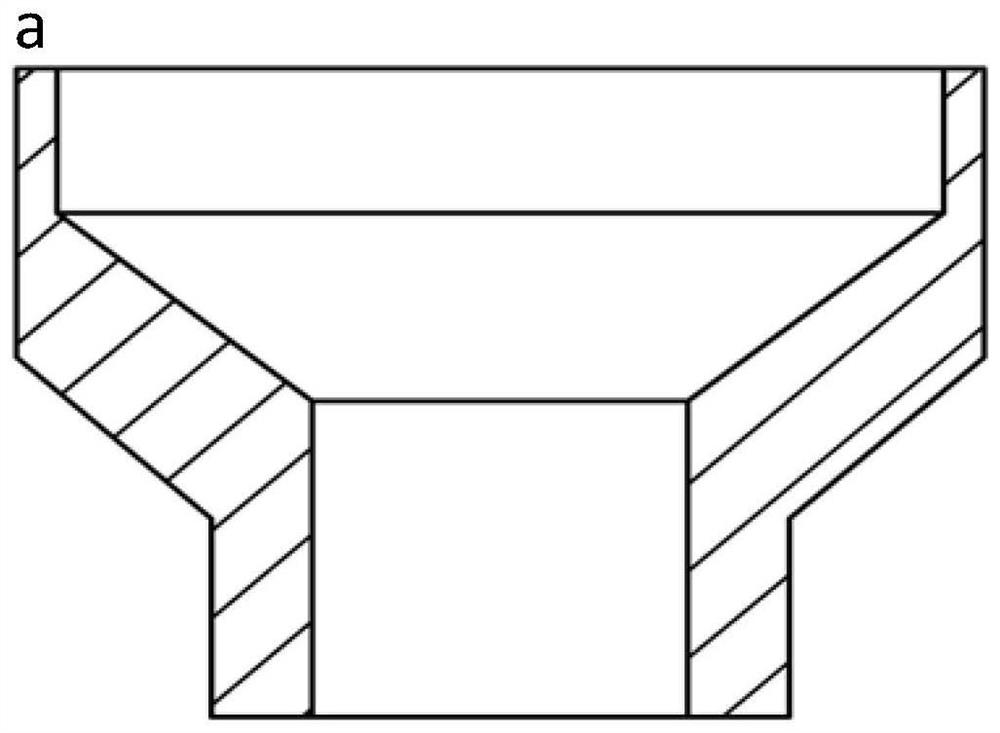
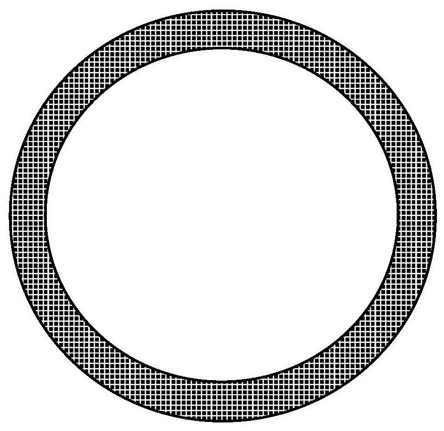
[0039] 1) the graphite is processed into a knife-edge annular graphite cathode substrate, the outer diameter of the knife-edge annular graphite cathode substrate (i.e. the diameter of the outer ring) is 50 mm, and the wall thickness (i.e. the radius of the outer ring minus the radius of the inner ring) is 1 mm; Ultrasonic cleaning in ethanol and drying in an oven for later use;

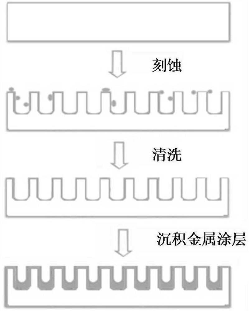
[0040] 2) By ultraviolet laser etching, a graphite microcolumn array is constructed on the surface of the knife edge of the dried knife-edge annular graphite cathode substrate. The diameter of the graphite microcolumn is 20 μm, and the ratio of height to diameter is 6:1. The distance between the micro-column axes is 60 μm, and the graphite cathode of the micro-column array is obtained, which is cleaned with low-power ultrasonic in ethanol to remove the debris around the graphite micro-column, and dried in an oven for later use;

[0041] 3) Place the dried microcolumn array graphite cathode in a chemic...

Embodiment 2

[0047] 1) the graphite is processed into a knife-edge annular graphite cathode substrate, the outer diameter of the knife-edge annular graphite cathode substrate (i.e. the diameter of the outer ring) is 100 mm, and the wall thickness (i.e. the radius of the outer ring minus the radius of the inner ring) is 1.5 mm; Ultrasonic cleaning in ethanol and drying in an oven for later use;

[0048] 2) By ultraviolet laser etching, a graphite microcolumn array is constructed on the surface of the knife edge of the dried knife-edge annular graphite cathode substrate. The diameter of the graphite microcolumn is 40 μm, and the ratio of height to diameter is 5:1. The distance between the micro-column axes is 100 μm, and the graphite cathode of the micro-column array is obtained, which is cleaned with low-power ultrasonic in ethanol to remove the debris around the graphite micro-column, and dried in an oven for later use;

[0049] 3) Place the dried microcolumn array graphite cathode in a ch...

Embodiment 3

[0054] 1) the graphite is processed into a knife-edge annular graphite cathode substrate, the outer diameter of the knife-edge annular graphite cathode substrate (i.e. the diameter of the outer ring) is 50 mm, and the wall thickness (i.e. the radius of the outer ring minus the radius of the inner ring) is 1 mm; Ultrasonic cleaning in ethanol and drying in an oven for later use;

[0055] 2) By ultraviolet laser etching, a graphite microcolumn array is constructed on the surface of the knife-edge annular graphite cathode substrate after drying. The diameter of the graphite microcolumn is 5 μm, and the ratio of height to diameter is 20:1. The adjacent graphite The distance between the micro-column axes is 20 μm, and the graphite cathode of the micro-column array is obtained, which is cleaned with low-power ultrasonic in ethanol to remove the debris around the graphite micro-column, and placed in an oven to dry for later use;

[0056] 3) Place the dried microcolumn array graphite ...


PUM

PropertyMeasurementUnit
Thicknessaaaaaaaaaa
Thicknessaaaaaaaaaa
Outer diameteraaaaaaaaaa

Abstract

The invention relates to a microwave maser, and concretely relates to a long-service-life micro-column array graphite and metal composite cathode structure for the microwave maser, and a preparation method thereof. The invention aims to solve the technical problems that the existing micro-column graphite cathode structure loses the effect of stably emitting electron beams due to the fact that a convex emission structure is seriously consumed and even completely loses the convex emission structure, and the porous structure of a graphite material is easy to release gas after being bombarded by electron beams, so the vacuum degree of the system is reduced, the coupling efficiency of beam waves is reduced, and the insulativity of system devices is reduced. The cathode structure comprises a micro-column array graphite cathode, and the micro-column array graphite cathode comprises a knife-edge-shaped annular graphite cathode base body and a plurality of graphite micro-columns arranged on the surface of a knife edge of the knife-edge-shaped annular graphite cathode base body in an array mode. The cathode structure is characterized in that metal coatings are uniformly adhered to the surface of the knife-edge-shaped annular graphite cathode base body and the top ends and the side walls of the graphite micro-columns, and the metal coatings are made of refractory metal.

Description

technical field [0001] The invention relates to a microwave maser, in particular to a composite cathode structure of long-life microcolumn array graphite and metal for a microwave maser and a preparation method thereof. Background technique [0002] The repetition rate relativistic return wave tube is a high-power microwave source with great development potential. The cathode of the relativistic return wave tube is its key component, which is mainly used to generate high-current electron beams driven by high-power pulses. With the development of high-power microwave devices towards higher average power, the cathode is required to have characteristics such as high current emission density, long life, short rise time of electron beam, low plasma expansion speed, and good stability of emitted electron beam (defense Mentioned in Hua Ye's dissertation "Research on Intensive Electron Beam Emission and Collection Characteristics of Carbide Modified Graphite Materials" in 2019 at t...

Claims


Application Information

Patent Timeline
IPC IPC(8): H01J23/04H01J25/46
CPCH01J23/04H01J25/46
Inventor 程军刘文元柯昌凤霍艳坤陈昌华孙钧张贝
Owner NORTHWEST INST OF NUCLEAR TECH
Why Eureka
Try Eureka