Multi-channel, self-calibrating fiber-coupled raman spectrometers including diagnostic and safety features

a fiber-coupled, raman spectrometer technology, applied in the field oframan spectroscopy, can solve the problems of less stable emission wavelengths of solid-state lasers more common in process raman, insufficient wavelength calibration of the spectrograph alone, and insufficient laser coupling efficiency to analyze raman shifts with the greatest possible accuracy, etc., to achieve quasi-simultaneous or sequential calibration/data acquisition, optimize laser coupling efficiency, and high density multi-channel channel operation

Active Publication Date: 2005-07-28
ENDRESS + HAUSER OPTICAL ANALYSIS INC
View PDF11 Cites 55 Cited by
  • Summary
  • Abstract
  • Description
  • Claims
  • Application Information

AI Technical Summary

Benefits of technology

[0015] In the preferred embodiment, dedicated calibration channels surround data channels on a 2-dimensional CCD dispersed slit image implemented using a unique cabling architecture. This “over/under” calibration interpolation approach facilitates quasi-simultaneous or sequential calibration/data acquisitions. CCD binning between sequential calibration and data acquisitions enables higher density multi-channel operation with tilted images based upon a

Problems solved by technology

Such remote spectral analysis presents technical challenges, however, including the strong scattering signature of the material used for the optical fiber, this interference potentially being generated by both the laser excitation in the illumination fiber and any strong Rayleigh (unshifted) scattering allowed to enter the collection fiber.
These spurious fiber signatures can compete with, or even overshadow, the desired signature of the sample under test, particularly when

Method used


Image

  • Multi-channel, self-calibrating fiber-coupled raman spectrometers including diagnostic and safety features
  • Multi-channel, self-calibrating fiber-coupled raman spectrometers including diagnostic and safety features
  • Multi-channel, self-calibrating fiber-coupled raman spectrometers including diagnostic and safety features

Examples


Embodiment Construction

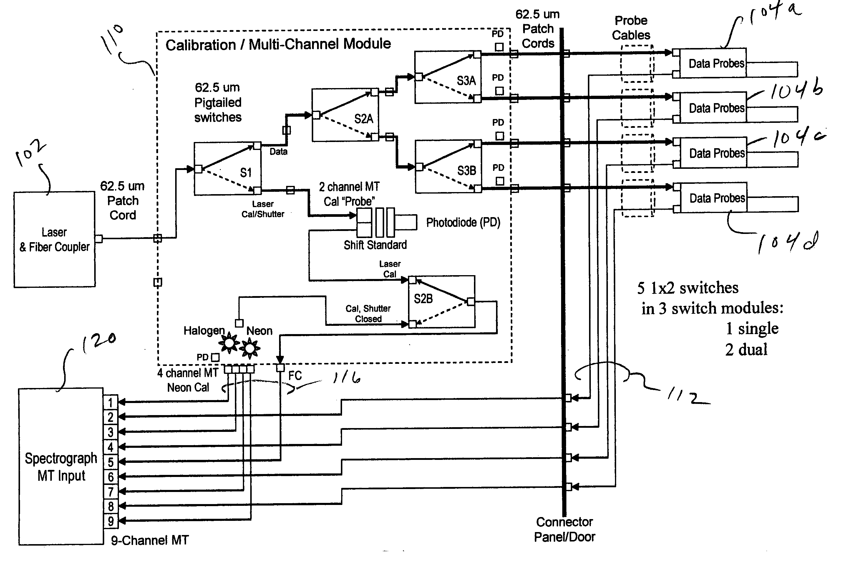
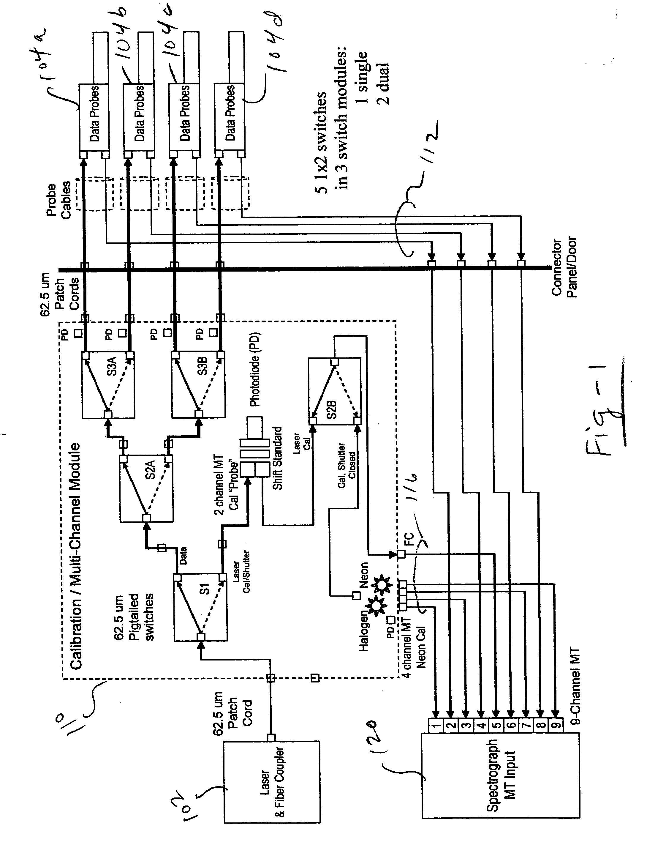
[0038]FIG. 1 is a system block diagram of a 1 laser, 4 probe configuration according to the invention. The laser and fiber coupler is shown at 102, and the probes are shown at 104A through 104D. The probes may use any fiber-coupled type of configuration, including those depicted in U.S. Pat. Nos. 5,377,004; 5,862,273; 5,943,128; 5,974,211; 6,038,363; 6,351,306; and 6,603,545, the entire of content of each being incorporated herein by reference. More particularly, the various filters contained in the probes 104A, 104B, 104C, and 104D may utilize holographic, dielectric, fiber-integrated, and so forth.

[0039] The laser 102 and probes 104 are interfaced to a calibration / multi-channel module 110 through optical cables and patch cords. The module 110 in this case includes five low-loss 1×2 optical switches which may be procured from Luminos Industries. The switches, S-1, S-2A, S-3A, S-3B and S-2B route the laser to the data probes and calibration sources, as explained in further detail b...


PUM


Abstract

A multi-channel, reconfigurable fiber-coupled Raman instrument uses fiber optic switches for laser and calibration light routing to facilitate automated calibration, diagnosis and operational safety. The system allows wavelength axis calibration on all channels; laser wavelength calibration (including multiple and/or backup laser options); fiber coupling optimization; fault detection/diagnosis; and CCD camera binning setup. In the preferred embodiment, dedicated calibration channels surround data channels on a 2-dimensional CCD dispersed slit image implemented using a unique cabling architecture. This “over/under” calibration interpolation approach facilitates quasi-simultaneous or sequential calibration/data acquisitions. CCD binning between sequential calibration and data acquisitions enables higher density multi-channel operation with tilted images based upon a multiplexed grating configuration. A diamond sample is used as a Raman shift reference for laser calibration, preferably in the form of a small disc sampled with an edge-illuminating probe using two unfiltered fibers. Detection of beam transmitted through the diamond reference is also used to optimize laser coupling efficiency with motion servos. An “intrinsically safe” laser interlock circuit also serves as current source for probe head “laser on” diode indicator. The integrity of key components is monitored through strategically placed photodiodes positioned, for example, at fiber bends to detect light leakage from bent fiber as verification of commanded laser path through fiber switches and at neon and halogen lamp locations to verify lamp operation. The optical switches used for calibration may also be configured for use as a laser shutter.

Description

FIELD OF THE INVENTION [0001] This invention relates generally to Raman spectroscopy and, more particularly, to multi-channel spectrometers including self-calibrating, diagnostic and safety features. BACKGROUND OF THE INVENTION [0002] Induced radiative effects such as Raman scattering and fluorescence have become extremely valuable tools associated with the non-destructive determination of molecular constituents. To characterize a composition in a remote or hostile environment, optical fibers may advantageously be used to deliver excitation energy to a sample under investigation and to carry scattered radiation back to instrumentation for spectral analysis. An excitation source path may take the form of a laser providing a stimulus at an appropriate wavelength coupled to an input fiber, and a collection path may be made up of a second fiber carrying return radiative information to a spectral analysis tool such as a spectrograph. [0003] In some instances, laser energy is now transpor...

Claims


Application Information

Patent Timeline
IPC IPC(8): G01J3/02G01J3/28G01J3/44G01N21/27G01N21/65
CPCG01J3/02G01J3/0218G01J3/027G01J3/10G01J3/28G01N2201/12723G01J3/44G01J2003/2866G01N21/274G01N21/65G01J3/2803
Inventor TEDESCO, JAMES M.SLATER, JOSEPH B.DAVIS, KEVIN L.FAIRCHILD, RONALD C.BAUGHN, JOHN W.
Owner ENDRESS + HAUSER OPTICAL ANALYSIS INC
Why Eureka
Try Eureka