Rock sample high-precision cutting equipment and method

A technology of rock samples and cutting equipment, which is applied in the direction of stone processing equipment, test sample preparation, sampling, etc., can solve the problems of poor cutting accuracy, inability to adjust the cutting thickness accurately, and low cutting efficiency, so as to reduce grinding time and improve Sample preparation efficiency and good cutting effect

Active Publication Date: 2021-07-13
INST OF MINERAL RESOURCES CHINESE ACAD OF GEOLOGICAL SCI
View PDF14 Cites 1 Cited by
  • Summary
  • Abstract
  • Description
  • Claims
  • Application Information

AI Technical Summary

Problems solved by technology

[0005] In view of the above analysis, the present invention aims to provide a high-precision cutting equipment and method for rock samples to solve the problems of poor cutting accuracy, low cutting efficiency and inability to accurately adjust the cutting thickness of existing rock cutting equipment

Method used


Image

  • Rock sample high-precision cutting equipment and method
  • Rock sample high-precision cutting equipment and method
  • Rock sample high-precision cutting equipment and method

Examples


Embodiment 1

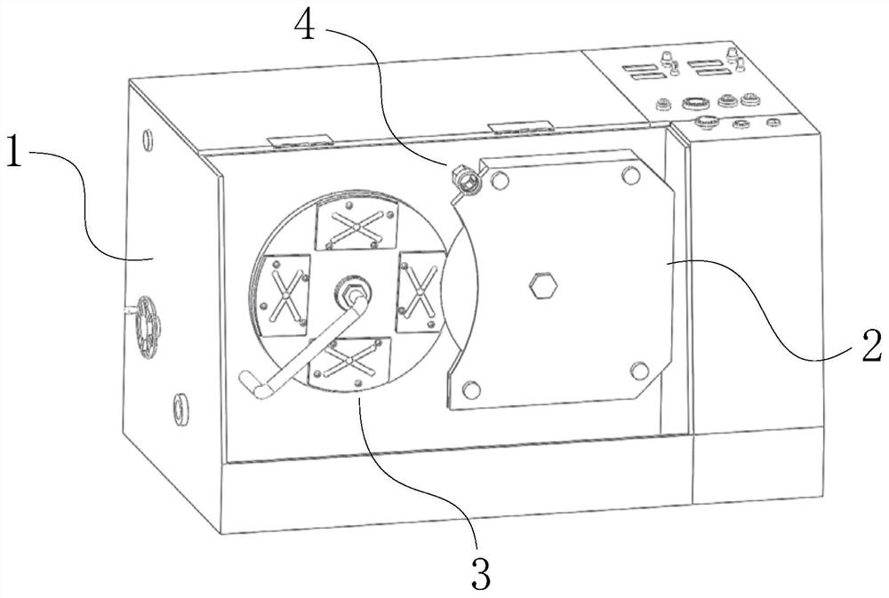
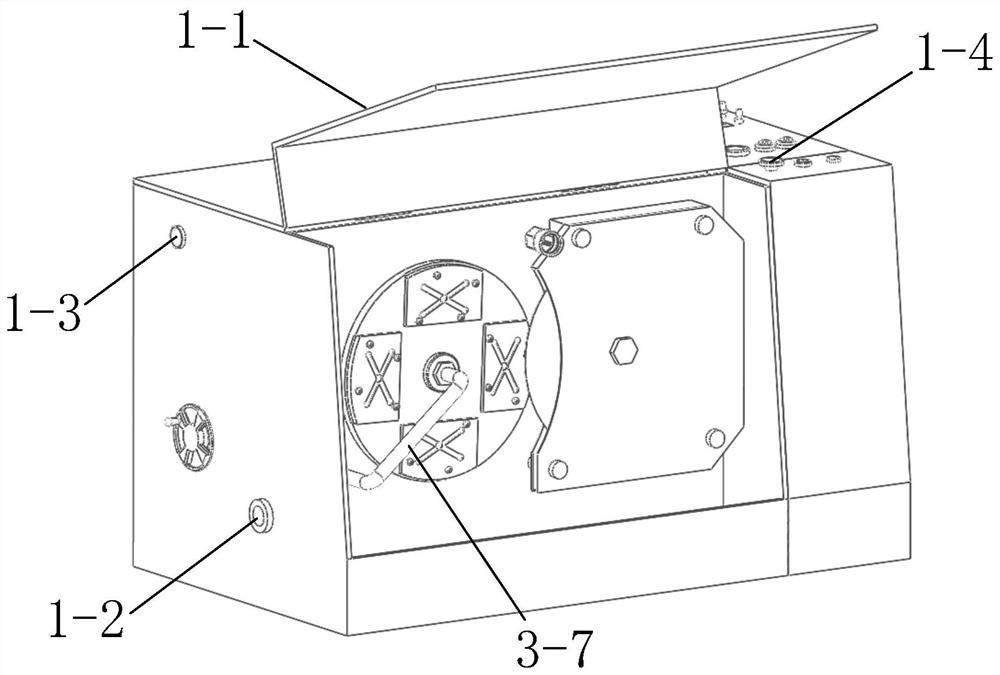
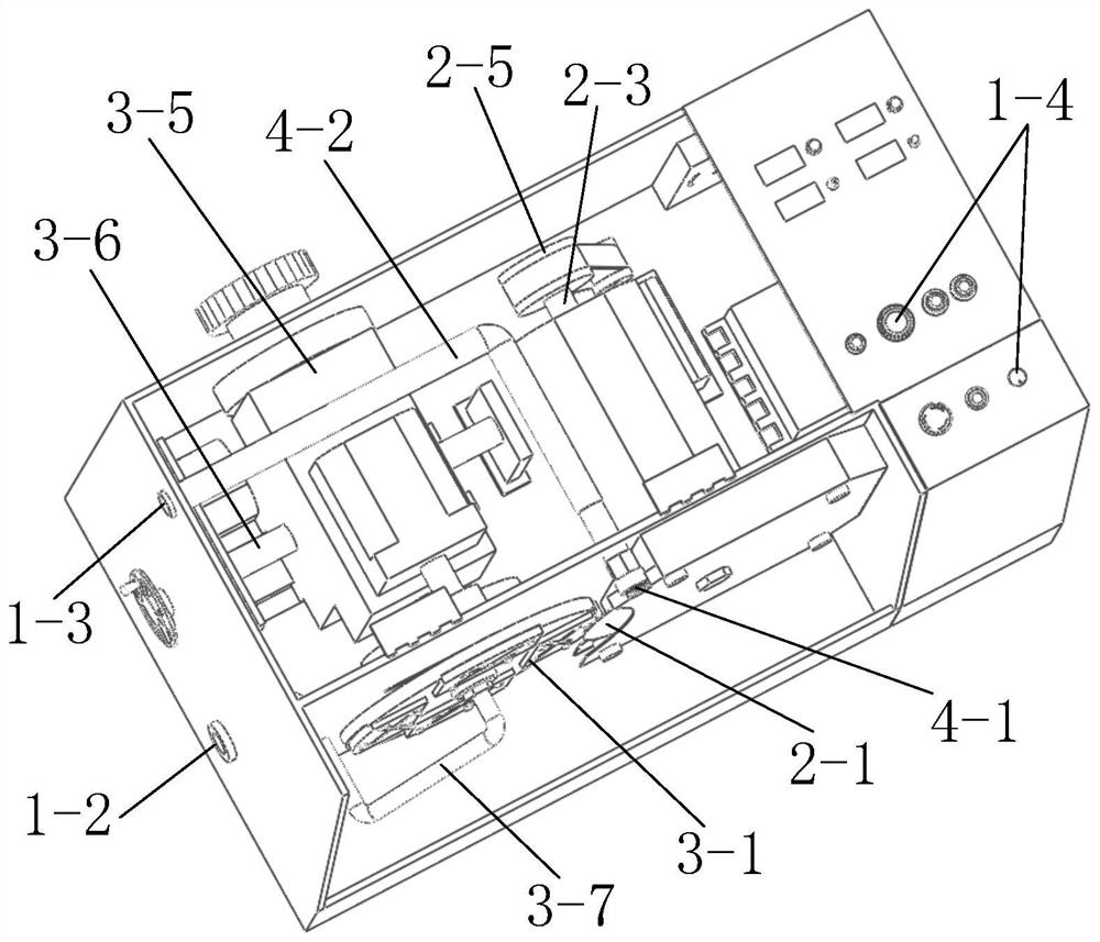
[0074] A specific embodiment of the present invention, such as Figure 1 to Figure 4 As shown, a rock sample high-precision cutting device is disclosed, including:

[0075] The cutting mechanism 2 includes a cutter head 2-1 and a first drive motor 2-2 for driving the cutter head 2-1 to rotate;

[0076] The clamping mechanism 3 includes a sample loading tray 3-1 and a driving mechanism. A plurality of sample mounting parts are evenly distributed on the sample loading tray 3-1. The samples to be cut are fixed on the sample mounting parts, and the driving mechanism is used to drive the sample loading tray 3-1. 1 Approaching or moving away from the cutter head 2-1 at a set speed while rotating;

[0077] The machine base 1, the cutting mechanism 2 and the rock sample clamping mechanism 3 are arranged on the machine base 1.

[0078] When cutting, the rock sample is fixed on the glass slide, and then the glass slide is fixed on the sample mounting part on the sample tray 3-1; -1 r...

Embodiment 2

[0108] Since the thickness of the rock samples to be cut is mostly 1-2cm, and the lateral movement speed of the sample loading plate 3-1 and the rotation speed of the cutter head 2-1 during the cutting process will affect the cutting effect, especially when the cutting starts instantaneously, if the sample loading If the transverse speed of the disk 3-1 is too fast, it will easily cause the rock sample to be cut to crack, resulting in the failure of cutting the sample. Therefore, it is necessary to control the advancing speed and rotation speed of the sample-carrying disc 3-1 at the moment of cutting and during the cutting process. The transverse propulsion speed of the sample-carrying disc 3-1 should be slow and maintain a stable transverse propulsive speed during the cutting process. However, there is a certain distance between the initial position of the sample-carrying disc 3-1 and the cutter head 2-1. If the device starts to move laterally at a slow speed, the sample-carry...

Embodiment 3

[0116] Another specific embodiment of the present invention discloses a method for high-precision cutting of rock samples, using the high-precision cutting equipment for rock samples in Embodiment 1 or 2, specifically including the following steps:

[0117] Step 1: Fix the rock sample to be cut on the glass slide.

[0118] Paste and fix the cube-shaped rock sample to be cut on the first side of the glass slide, and load the glass slide containing the rock sample to be cut into the adsorption installation groove 3-1-1 of the sample tray 3-1, the glass The second side of the slide is in contact with the adsorption surface of the adsorption installation groove 3-1-1;

[0119] Step 2: Start the vacuum device, and stably adsorb the glass slide on the sample loading tray 3-1 by means of vacuum adsorption.

[0120] Use a vacuum pump to extract the gap between the glass slide and the adsorption installation groove 3-1-1 and the air in the vacuum tube, and the internal passage forms a...


PUM

PropertyMeasurementUnit
thicknessaaaaaaaaaa

Abstract

The invention discloses rock sample high-precision cutting equipment and method, and belongs to the technical field of rock cutting equipment. The problems that existing rock cutting equipment is poor in cutting precision and low in cutting efficiency, and the cutting thickness cannot be adjusted are solved. The rock sample high-precision cutting equipment comprises a machine base, a cutting mechanism and a clamping mechanism, the cutting mechanism and the clamping mechanism are fixed to the machine base, and the cutting mechanism comprises a cutterhead and a first driving motor used for driving the cutterhead to rotate. The clamping mechanism comprises a sample loading disc and a driving mechanism, a plurality of sample mounting parts are uniformly distributed on the sample loading disc, to-be-cut samples are fixed on the sample mounting parts, and the driving mechanism is used for driving the sample loading disc to rotate while approaching or leaving the cutterhead at a set speed. The equipment is simple in structure and convenient to operate, the cutting thickness of the rock sample can be accurately adjusted, the cutting process is automatic, operation of professionals is not needed, the cutting efficiency is remarkably improved, and the equipment has wide application prospects.

Description

technical field [0001] The invention relates to the technical field of rock sample cutting equipment, in particular to a high-precision rock sample cutting equipment and method. Background technique [0002] Rock thin section identification is an important method often used in geological prospecting. [0003] At present, the production process of rock thin sections is as follows: first, use rock cutting equipment to cut rocks collected in the field, and cut them into rock sample blocks with a structure similar to a small cuboid, and try to cut the rock sample blocks as thin as possible during the cutting process; Shaped rock sample blocks are fixed and pasted on glass slides, and the rock sample blocks on the glass slides are ground and thinned to the required thickness by grinding equipment; finally, the rock samples thinned to the required thickness are polished, thereby Finished making the rock slices. [0004] However, the existing rock cutting equipment cannot accurat...

Claims


Application Information

Patent Timeline
Patent Type & Authority Applications(China)
IPC IPC(8): B28D1/24B28D7/00B28D7/04G01N1/28
CPCB28D1/24B28D7/005B28D7/046G01N1/286G01N2001/2873
Inventor 郭唯明
Owner INST OF MINERAL RESOURCES CHINESE ACAD OF GEOLOGICAL SCI
Why Eureka
Try Eureka