
Blockage removing system and application thereof

A system and plug-removing technology, applied in other gas emission reduction technologies, climate sustainability, chemical instruments and methods, etc., can solve problems such as space limitations on offshore platforms, improve oil and gas seepage capacity, and increase the scope of reservoir reconstruction. , the effect of reducing the reaction rate

Active Publication Date: 2021-07-13
CHINA OILFIELD SERVICES
View PDF8 Cites 1 Cited by
  • Summary
  • Abstract
  • Description
  • Claims
  • Application Information

AI Technical Summary

Problems solved by technology

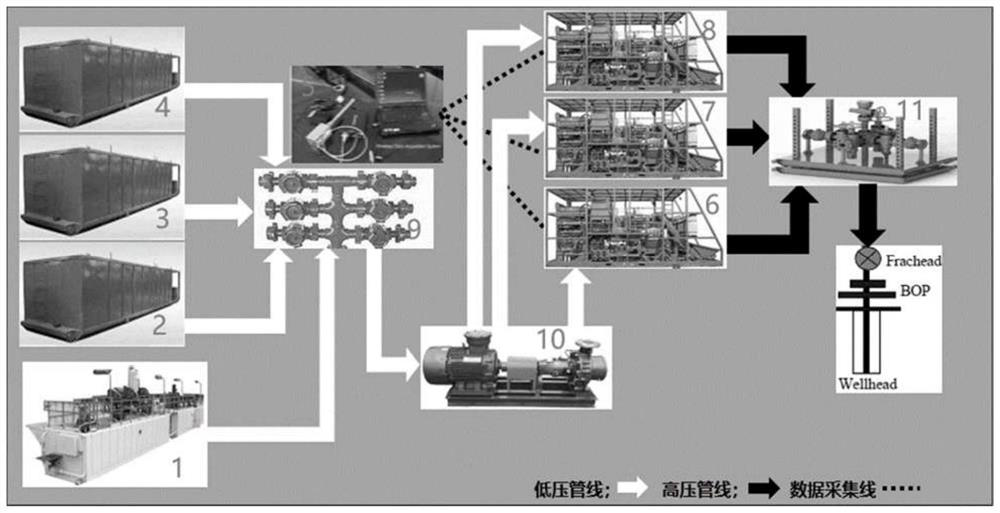
The blockage-removing fluid is prepared in the mud pool of the offshore platform, and the displacement fluid is prepared in the buffer tank of the offshore platform, which can solve the space limitation problem of the offshore platform

Method used


Image

  • Blockage removing system and application thereof
  • Blockage removing system and application thereof
  • Blockage removing system and application thereof

Examples


Embodiment 1

[0051] In this embodiment, the chelating agent is tetrasodium glutamic acid diacetate, purchased from Tianjin Development Zone Over Industry and Trade Co., Ltd.;

[0052] The first surfactant in the plugging solution is a fluorocarbon surfactant (C 8 f 17 SO 2 NHC 3 h 7 NR 2 (O)), purchased from Tianjin Development Zone Over Industry and Trade Co., Ltd.; surface tension is 21mN / m;

[0053] The corrosion inhibitor is Mannich base quaternary ammonium salt corrosion inhibitor (high temperature acidification corrosion inhibitor), purchased from Tianjin Juli Polymer Petroleum Engineering Technology Co., Ltd.;

[0054] The second surfactant in the drag-reducing acid is a fluorocarbon surfactant (C 8 f 17 SO 2 NHC 3 h 7 NR 2 (O)), purchased from Tianjin Development Zone Over Industry and Trade Co., Ltd.; surface tension is 21mN / m;

[0055] Stabilizer is citric acid, purchased from Tianjin Development Zone Over Industry and Trade Co., Ltd.;

[0056] Stabilizer is glycidyl...

Embodiment 2

[0071] Core Flow Experiment of Blockage Removing Fluid + Restraining Acid Slug Combination

[0072] (1) At a constant temperature of 95°C, use a core flow meter device to squeeze the configured plugging solution identical to that of Example 1 into the core from the positive end of the core holder (the core is the core of the target formation in Example 1), and observe When the pressure changes, the injection of the plugging solution is stopped when the injection volume of the plugging solution reaches 1 times the pore volume;

[0073] (2) Take out the rock core, carry out CT scanning to the rock core, as Figure 7 as shown in a;

[0074] (3) Squeeze the configured drag-reducing acid identical to that in Example 1 into the core from the positive end of the core holder, observe the pressure change, and stop the injection of the drag-reducing acid when the injection amount reaches 1 times the pore volume ;

[0075] (4) Take out the rock core, carry out CT scanning to rock core...


PUM

PropertyMeasurementUnit
surface tensionaaaaaaaaaa
breaking strengthaaaaaaaaaa
surface tensionaaaaaaaaaa

Abstract

The invention discloses a blockage removing system. The blockage removing system comprises blockage removing liquid, wherein the blockage removing liquid comprises a chelating agent and a first surface active agent; the chelating agent is one or more than one selected from a group consisting of disodium ethylene diamine tetraacetate, trisodium ethylene diamine tetraacetate, tetrasodium ethylene diamine tetraacetate, trisodium nitrilotriacetate and tetrasodium glutamate diacetate; and the surface tension of the first surface active agent is 19 mN / m to 22 mN / m. The blockage removing system provided by the invention is easy to operate and implement on site, can effectively solve many bottleneck problems such as narrow space of a working platform, ultrahigh temperature, high friction resistance and the like confronted by acid fracturing of an offshore deep-layer ultrahigh-temperature carbonate rock reservoir at present, realizes deep transformation of the offshore deep-layer ultrahigh-temperature carbonate rock reservoir, and effectively releases the productivity of the reservoir.

Description

technical field [0001] This article involves but is not limited to the field of offshore deep / ultra-deep and low-permeability oil and gas exploration and development technology, especially involves but is not limited to a plugging removal system and its application. Background technique [0002] The carbonate rock target formation in an oilfield in the Bohai Sea has a buried depth of more than 5000m and a temperature of more than 200°C, which is a deep ultra-high temperature carbonate rock reservoir. The reservoir minerals are mainly dolomitic limestone and limestone dolomite. The reservoir space is dominated by pores, and fractures are partially developed (some fractures are filled with calcite); the distribution of pores is uneven, and the total pores are low, which is an ultra-low porosity-ultra-low permeability reservoir. The reservoir fluid is mainly natural gas, containing hydrogen sulfide. In the process of exploration and development of oil and gas reservoirs, due ...

Claims


Application Information

Patent Timeline
Patent Type & Authority Applications(China)
IPC IPC(8): C09K8/74
CPCC09K8/74Y02P90/70
Inventor 崔波冯浦涌潘定成荣新明丁文刚杨国威张洪菁杜勋李翔王春林吴广张强陈军
Owner CHINA OILFIELD SERVICES
Learn More