System and method for rapidly disinfecting surface pathogenic microorganisms by array jet plasma

A technology of jet plasma and pathogenic microorganisms, used in disinfection, sanitary equipment for toilets, water supply devices, etc., can solve the problems of small coverage area, difficult power matching, high energy consumption, etc., to reduce harmful gas production, breakthrough technology Bottleneck, Reinforcement Effect Effect

Active Publication Date: 2021-07-16
BEIHANG UNIV
View PDF6 Cites 2 Cited by
  • Summary
  • Abstract
  • Description
  • Claims
  • Application Information

AI Technical Summary

Problems solved by technology

[0004] However, the traditional plasma jet kills a small coverage area, which is only suitable for micro-area treatment such as skin and teeth, and cannot meet the application requirements of industrial large-scale disinfecting (such as pathogenic microorganisms on the outer surface of the packaging box) and other scenarios.
Conventional arrayed atmospheric pressure jets are affected by problems such as uneven gas distribution, difficult power supply matching, and high energy consumption, so it is difficult to ensure the uniformity of discharge and jet stability

Method used


Image

  • System and method for rapidly disinfecting surface pathogenic microorganisms by array jet plasma
  • System and method for rapidly disinfecting surface pathogenic microorganisms by array jet plasma
  • System and method for rapidly disinfecting surface pathogenic microorganisms by array jet plasma

Examples


Embodiment 1

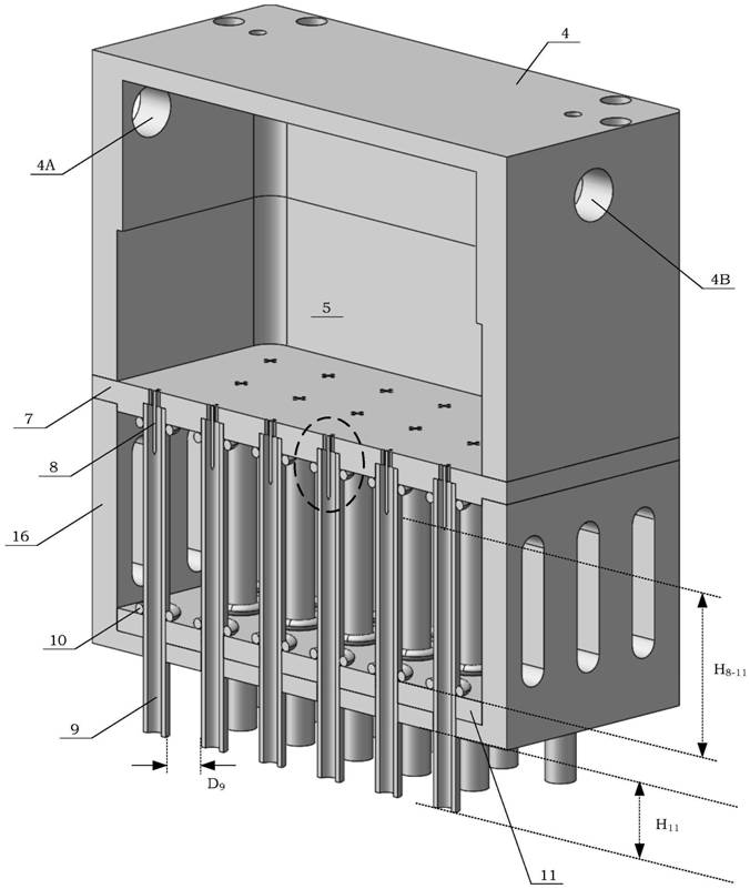
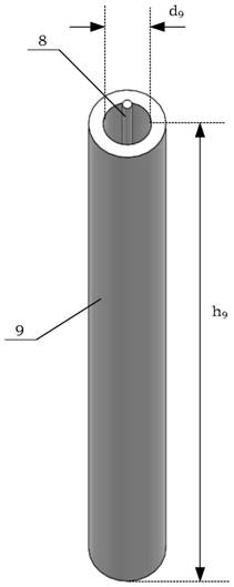
[0087] In Embodiment 1, the box size of the jet plasma subsystem 40 (such as image 3 shown), the length is denoted as A, the width is denoted as B, and the height is denoted as C, with a length of 150mm, a width of 150mm, and a height of 130mm, including 33 hollow medium pipes (9) arranged in an array, and the distance between adjacent hollow medium pipes ( D. 9 ) is 8mm. The diameter of the restrictor hole (6) is 0.52mm, and the inner diameter of the hollow medium pipe (9) (d 9 ) is 8mm, the outer diameter is 13mm, the length (h 9 ) is 85mm. The distance (H 8-11 ) is 40mm, the distance (H 11 ) is 25mm. The effective killing area of ​​a single jet plasma subsystem 40 is 174.2cm 2 .

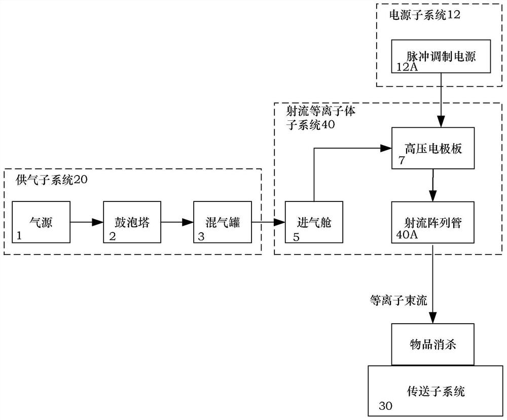
[0088] In Example 1, the gas composition is controlled by the gas supply subsystem 20 to be argon with a volume fraction greater than 99.9%, and the flow rate is 132 L / min, and then it is filled into the gas inlet chamber 5 of the jet plasma subsystem 40 and purged.

[0089] In Embodiment ...

Embodiment 2

[0093] In Embodiment 2, a jet plasma subsystem 40 of the same size as in Embodiment 1 is used.

[0094] In Embodiment 2, the gas composition is controlled by the gas supply system to be 95% argon by volume fraction, 5% oxygen, and the flow rate is 132L / min, which is then filled into the inlet chamber 5 of the jet plasma subsystem 40 and purged .

[0095] In Embodiment 2, under the atmosphere environment of the air inlet cabin 5 of the jet plasma subsystem 40, the modulated pulse power supply is switched on, and a high voltage of 10KV is applied to the high voltage electrode plate 7, and the sine frequency is adjusted to be 20kHz, and the pulse duty ratio is 60 %, the power of the power supply is 330w, and the voltage of the power supply is 200V, forming a large-area and uniform array plasma flow.

[0096] In Example 2, the object to be sterilized is placed on the conveying system, the distance between the hollow medium tube and the surface of the object is adjusted to be 15mm...

Embodiment 3

[0099] In Embodiment 3, a jet plasma subsystem 40 of the same size as in Embodiment 1 is used.

[0100] In Example 3, the gas composition is controlled by the gas supply system to be 95% argon by volume fraction, 2% N 2 O gas, with a flow rate of 132 L / min, is then filled into the intake chamber 5 of the jet plasma subsystem 40 and purged.

[0101] In Embodiment 3, under the atmosphere environment of the air inlet cabin 5 of the jet plasma subsystem 40, the modulated pulse power supply is switched on, a 15KV high voltage is applied to the high voltage electrode plate 7, and the sine frequency is adjusted to be 20kHz and the pulse duty ratio is 60. %, the power of the power supply is 330w, and the voltage of the power supply is 200V, forming a large-area and uniform array plasma flow.

[0102] In Example 3, the object to be sterilized is placed on the conveying system, the distance between the hollow medium tube and the surface of the object is adjusted to be 15 mm, and the co...


PUM

PropertyMeasurementUnit
pore sizeaaaaaaaaaa
diameteraaaaaaaaaa
lengthaaaaaaaaaa

Abstract

The invention discloses a system and method for rapidly disinfecting surface pathogenic microorganisms by array jet plasma. A gas supply subsystem (20) in the system comprises a gas source, a bubble tower and a gas mixing tank; a jet plasma subsystem (40) comprises a gas inlet cabin (5), a high-voltage electrode plate (7), a grounding electrode plate (11), hollow medium tubes (9), metal needles (8) and a fixed silica gel pad; and a power supply subsystem (12) and a transfer subsystem (30) are comprised. Mixed gas is introduced into the gas inlet cabin (5) connected with a power supply, so that working carrier gas forms large-area and uniform-density plasma; multi-tube uniform flow distribution is implemented through flow limiting holes (6), and a needle-ring discharge type array electrode is formed; Useless power consumption is reduced by modulating a pulse source, the composition and concentration level of active components of a plasma flow are controlled through atmosphere composition, and disinfecting time is controlled through speed regulation and control of a transfer system. According to the device and the method of the invention, the pathogenic microorganisms on the surface of an object can be quickly disinfected in a large area with low energy consumption under the conditions of normal temperature, refrigeration and freezing.

Description

technical field [0001] The present invention relates to the technical field of disinfecting surface pathogenic microorganisms, and more particularly refers to a system and method for rapidly disinfecting surface pathogenic microorganisms with array jet plasma. Background technique [0002] Low-temperature plasma (Non-thermal Plasma, NTP) is also known as non-equilibrium plasma. During the entire process of plasma formation, the temperature (ie energy) of electrons reaches 1-20eV, but the temperature of other particles is lower. , almost equal to room temperature, in a state of complete disequilibrium. Plasma contains a large number of active ions, such as positive and negative ions, photons, high-energy electrons and free radicals, etc. These active ions can be used to kill pathogenic microorganisms (such as bacteria, viruses, etc.). [0003] Plasma jet is an important form of discharge in disinfecting pathogenic microorganisms. This technology consists of a tube-type disc...

Claims


Application Information

Patent Timeline
Patent Type & Authority Applications(China)
IPC IPC(8): A61L2/14A61L2/26
CPCA61L2/14A61L2/26A61L2202/11
Inventor 李想申芳霞阴勇杨毅
Owner BEIHANG UNIV
Why Eureka
Try Eureka