
Amorphous alloy continuous casting machine and continuous casting method thereof

An amorphous alloy and continuous casting machine technology, applied in the field of metal material casting, can solve the problems of increased production cost, low production efficiency, and restrictions on the large-scale industrial application of amorphous alloys, and achieves easy replacement and disassembly, simple device structure, space-saving effect

Pending Publication Date: 2021-07-16
YANSHAN UNIV
View PDF9 Cites 0 Cited by
  • Summary
  • Abstract
  • Description
  • Claims
  • Application Information

AI Technical Summary

Problems solved by technology

[0003] Since the first use of rapid solidification technology to prepare amorphous alloy strips in 1960, people have gradually realized the importance of amorphous alloys and began to devote themselves to the study of preparation methods for amorphous alloys. Although continuous casting and continuous preparation of amorphous alloys have been developed The twin-roll quenching rolling method and the single-roll centrifugal chilling method of state alloys prepare amorphous thin strips or amorphous wires, but the thickness is at the micron level, which limits the application of amorphous alloys in some fields; The preparation process of crystal alloys includes copper mold suction casting method, powder metallurgy technology, melt water quenching method, die casting method, etc. The above methods are limited to the production of amorphous alloys with fixed specifications, and cannot realize continuous casting of amorphous alloys. Low, different molds are required to produce billets of different specifications, which increases production costs and also limits the large-scale industrial application of amorphous alloys

Method used


Image

  • Amorphous alloy continuous casting machine and continuous casting method thereof
  • Amorphous alloy continuous casting machine and continuous casting method thereof
  • Amorphous alloy continuous casting machine and continuous casting method thereof

Examples


Embodiment 1

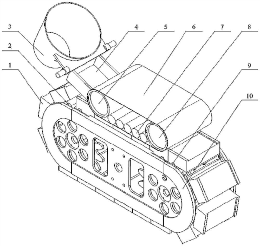
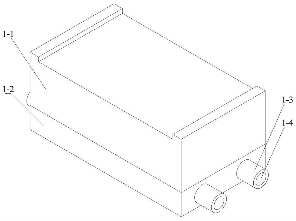
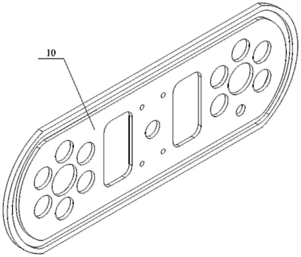
[0025] Such as Figures 1 to 3 As shown, this embodiment provides an amorphous alloy continuous casting machine, including a frame 10, a plurality of moving blocks 1, a molten pool 3, a sealing mechanism and a driving mechanism; guide rails are provided inside the frame 10, and the multiple A moving block 1 is movably arranged on the guide rail, and the moving block 1 is power-connected with the driving mechanism; the melting pool 3 is arranged above one end of the frame 10, and the sealing mechanism is arranged on the machine Above the rack 10 and on top of the plurality of moving blocks 1 .

[0026] In this specific embodiment, the frame 10 includes two symmetrically arranged left and right parts, and the driving mechanism is arranged in the cavity between the left and right parts. The guide rail is an oblong closed-loop guide rail, and the linear part of the guide rail is arranged along the horizontal direction.

[0027] The moving block 1 is a block-shaped body, and both...

Embodiment 2

[0035] This embodiment discloses a continuous casting method comprising the amorphous alloy continuous casting machine in Embodiment 1, comprising the following steps:

[0036]a. Master alloy liquid pouring: the master alloy is melted in the molten pool 3, and the melted master alloy liquid is poured into the tundish 4 from the molten pool 3, and the master alloy liquid is injected into the steel strip from the tundish 4 under the action of static pressure or gas pressure In the casting cavity formed between 6 and the moving block 1, the mother alloy liquid is cooled and solidified by the moving block 1 in the casting cavity to form an amorphous alloy;

[0037] b, continuous casting: the driving wheel 2 rotates under the action of the power source, thereby driving the moving block 1 to move along the guide rail, and the moving block 1 drives the steel belt 6 to move synchronously along the continuous casting direction, and the master alloy liquid entering the casting cavity is ...


PUM

PropertyMeasurementUnit
widthaaaaaaaaaa
lengthaaaaaaaaaa

Abstract

The invention discloses an amorphous alloy continuous casting machine and a continuous casting method thereof, and relates to the technical field of metal material casting. The amorphous alloy continuous casting machine comprises a rack, multiple moving blocks, a molten pool, a sealing mechanism and a driving mechanism. A guide rail is arranged on the inner side of the rack, the multiple moving blocks are movably arranged on the guide rail, and the moving blocks are in power connection with the driving mechanism. The molten pool is arranged above one end of the rack, and the sealing mechanism is arranged above the rack and located at the tops of the multiple moving blocks. A rectangular casting cavity formed by the moving blocks and a steel belt realizes continuous casting of amorphous alloys with different specifications. The moving blocks and the steel belt move synchronously, so that the surface quality of an amorphous alloy cast blank is guaranteed. Solidification and output of amorphous alloys are completed in the casting cavity, the device structure is simple, and space is saved. Melt moves in the casting direction while being cooled and solidified in the casting cavity, continuous casting is achieved, and therefore the continuously-cast amorphous alloys are obtained. The moving blocks are mutually independent and are convenient to replace and disassemble when problems occur.

Description

technical field [0001] The invention relates to the technical field of metal material casting, in particular to an amorphous alloy continuous casting machine and a continuous casting method thereof. Background technique [0002] Amorphous alloy, also known as metallic glass, is a metastable material with long-range order and short-range disorder. Amorphous alloys do not have defects such as grain boundaries and stacking fault layers, so they have excellent properties that many crystalline materials do not have. As an emerging material, amorphous alloy has excellent properties such as high strength, high hardness, high wear resistance and high corrosion resistance, so it has great development potential and application prospects in precision machining, aerospace, national defense and military fields. [0003] Since the first use of rapid solidification technology to prepare amorphous alloy strips in 1960, people have gradually realized the importance of amorphous alloys and b...

Claims


Application Information

Patent Timeline
Patent Type & Authority Applications(China)
IPC IPC(8): B22D11/14B22D11/05
CPCB22D11/14B22D11/05B22D11/001
Inventor 刘日平任廷志马明臻杨二旭丁涛金昕刘大伟周奕年
Owner YANSHAN UNIV
Learn More