
Novel butterfly welding device

A butterfly, a new type of technology, applied in the field of new butterfly welding devices, can solve problems such as tab bumping, dry cell tab breakage, and difficult insertion into the shell, so as to improve product quality, reduce manual errors, and ensure consistency.

Active Publication Date: 2021-07-16
ZHEJIANG NARADA POWER SOURCE CO LTD +1
View PDF10 Cites 0 Cited by
  • Summary
  • Abstract
  • Description
  • Claims
  • Application Information

AI Technical Summary

Problems solved by technology

[0004] Compared with the quality of butterfly welding and dry battery assembly, the current lithium battery industry basically adopts the method of making dry batteries first (referring to laminating or winding the positive and negative electrodes and separators into batteries), and then making the pole ears of the dry batteries Welding with the lugs outside the production cell, the current aluminum shell battery basically adopts the laser welding process, firstly through ultrasonic welding to weld several dry cells to the connecting piece, and then connect the dry cell with the connecting piece to the pole of the cover plate Connection, the connection method basically adopts laser welding, so the quality of the battery core welded by butterfly welding directly affects the quality of the dry battery. If the ear is broken or the tab hits the wall, it will cause a short circuit. If the case is not well inserted, it will directly affect the electrical performance of the liquid injection, and there may even be serious battery problems.

Method used


Image

  • Novel butterfly welding device
  • Novel butterfly welding device
  • Novel butterfly welding device

Examples


Embodiment Construction

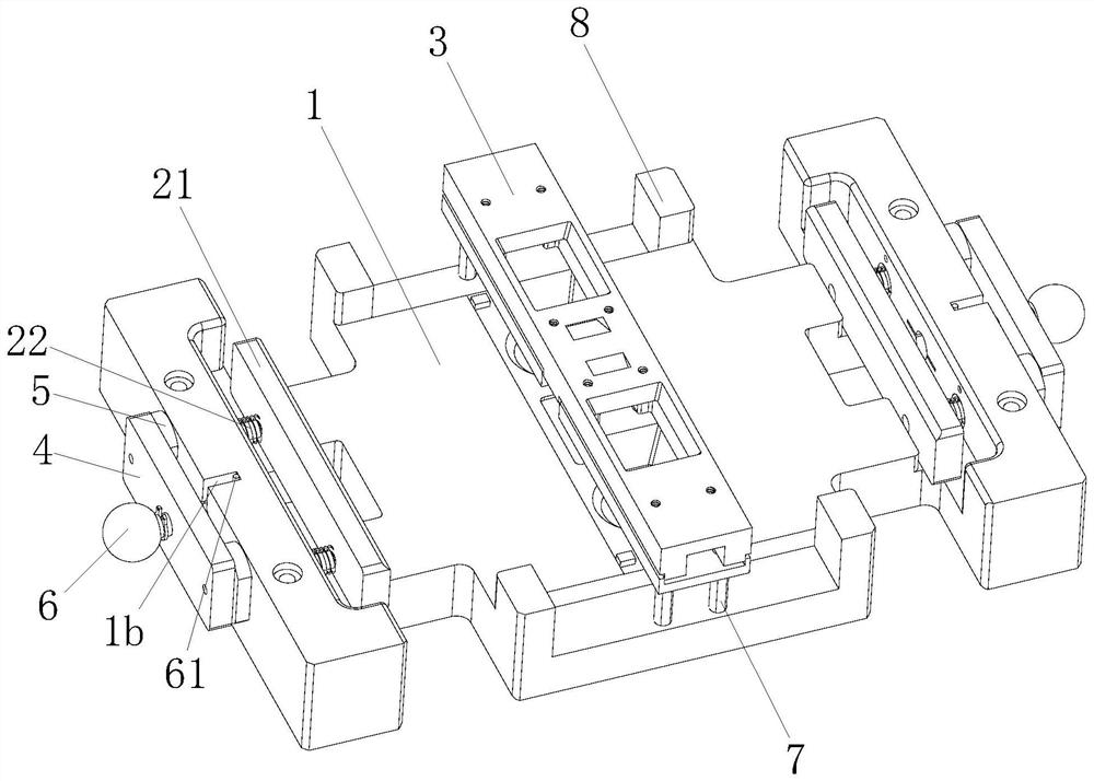
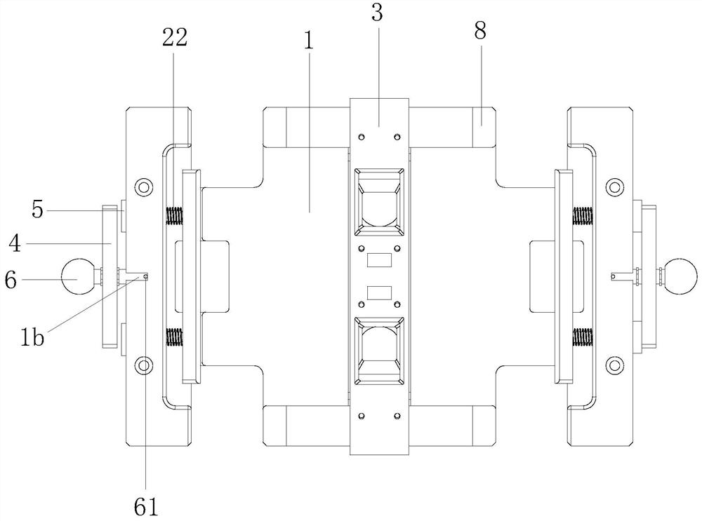
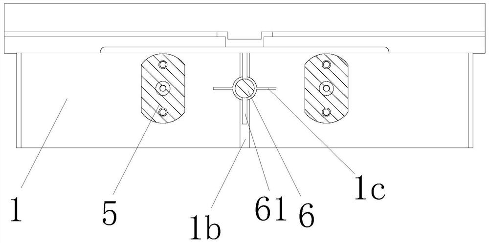
[0029] In order to further understand the content of the present invention, in conjunction with the attached Figure 1-5 And embodiment describe the present invention in detail.

[0030] combined with Figure 1-5 , a new type of butterfly welding device in this embodiment, including a positioning platform 1 for positioning the battery cover plate, dry cell and dry cell connecting piece; a cell position limiting and pre-tightening structure 2 for positioning the dry cell; The pressure head structure is used to position the battery cover plate and the dry cell connecting piece; the cell limit and pre-tightening structure 2 includes a pre-tightening plate 21, a pre-tightening spring 22 and a guide column 23, and the pre-tightening plate 21 is positioned at the position The inner side of the platform 1 can move toward one side to squeeze the dry cell. The pretension spring 22 is sleeved on the guide column 23, and the guide column 23 can move relative to the positioning platform ...


PUM


Abstract

The invention discloses a novel butterfly welding device which comprises a positioning platform, a battery cell limiting and pre-tightening structure and a pressure head structure. The positioning platform is used for positioning a battery cover plate, a dry battery cell and a dry battery cell connecting piece. The battery cell limiting and pre-tightening structure is used for positioning the dry battery cell. The pressure head structure is used for positioning the battery cover plate and the dry battery cell connecting piece. The battery cell limiting and pre-tightening structure comprises a pre-tightening plate, a pre-tightening spring and a guide column. The guide column is sleeved with the pre-tightening spring, and the pre-tightening spring is used for driving the pre-tightening plate to extrude the dry battery cell. The battery cell limiting and pre-tightening structure further comprises a limiting structure used for limiting the moving distance of the pre-tightening plate, and the pre-tightening spring is always in a compressed state. According to the technical problem of inaccurate dry battery cell limiting in the prior art, the novel butterfly welding device is provided and can play the effect in repeatedly limiting the position of the dry battery cell and ensuring the consistency of the position of the dry battery cell.

Description

technical field [0001] The invention relates to the technical field of lithium batteries, in particular to a novel butterfly welding device. Background technique [0002] The main core components of the aluminum shell battery include the battery cell, the aluminum shell, the cover plate, the electrolyte, the connecting piece, the PET film, the adhesive tape, etc. The performance and safety of the battery cell are self-evident, and the assembly quality of the battery cell directly Determine battery safety, electrical performance (capacity, energy, internal resistance, etc.) and electrochemical reaction, the battery assembly method mainly directly affects the quality of dry battery assembly, ultrasonic welding quality, laser welding quality and related raw material quality decisions. [0003] In addition, with the development of the industry and the requirements of national new energy-related standards, the demand for battery energy density is getting higher and higher. Lithiu...

Claims


Application Information

Patent Timeline
Patent Type & Authority Applications(China)
IPC IPC(8): B23K37/04H01M10/04H01M10/058
CPCB23K37/0426H01M10/0404H01M10/058B23K2101/36Y02P70/50Y02E60/10
Inventor 刘斯顺蒋岚相佳媛
Owner ZHEJIANG NARADA POWER SOURCE CO LTD
Learn More