Remote laying intelligent subsurface buoy dragged by unmanned ship
An unmanned, long-range technology, applied in the directions of unmanned surface ships, ships, buoys, etc., can solve the problems of expensive ship time consumption, difficulty in assembling the submarine, and inability to complete the deployment, and reduce the number of submarines. The probability of loss, improving the recovery rate of potential targets, and expanding the effect of accurate understanding
- Summary
- Abstract
- Description
- Claims
- Application Information
AI Technical Summary
Problems solved by technology
Method used
Image
Examples
Embodiment 1
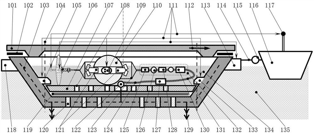
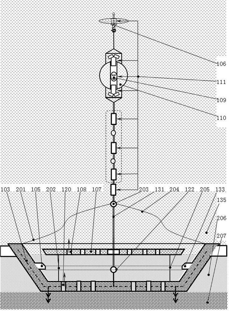
[0050] Embodiment 1: as figure 1 , 2 As shown, a remote deployment intelligent submarine towed by an unmanned boat includes a satellite communication device 106, a main floating ball 110, an ADCP 121, a controller 109, a stainless steel bracket 123, an instrument chain 132, an acoustic release device 127, an anchor chain 124, Connecting ring 122, boat-shaped counterweight 103, tow bar 114, release device 113 and water inlet device, the ADCP121 for upward and downward driving is respectively arranged on the main floating ball 110, and the controller 109 is arranged on the In the reserved cavity of the main floating ball 110, the stainless steel bracket 123 passes through the reserved hole on the main floating ball 110, and is fixed on the main floating ball 110 with nuts, and the upper part of the stainless steel bracket 123 is provided with In the satellite communication device 106, the lower part of the stainless steel bracket 123 is connected to the instrument chain 132 usi...
Embodiment 2
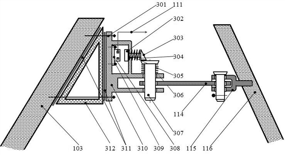
[0065] Embodiment 2: as figure 1 with image 3 As shown, the release device 113 includes a large bolt 301, a disc 302, a triangular block 303, a small spring 304, a connecting rod 305, a large spring 306, a cylindrical pin 307, a suction cup electromagnet 308, a small bolt 309, and a frame 310, rubber pad 311 and triangular pad 312, the large bolt 301 connects the frame 310, the rubber pad 311, the triangular pad 312 and the boat counterweight 103 into one; the controller 109 use the signal cable 111 to connect the power relay of the suction cup electromagnet 308 to control the operation or stop of the suction cup electromagnet 308; 310; one end of the connecting rod 305 is welded to the triangular block 303, the small spring 304 is sleeved on the connecting rod 305, and the connecting rod 305 passes through the frame 310 and is threadedly connected with the disc 302, The disk 302 is made of ferromagnetic material, and the parts exposed to seawater in this application are al...
Embodiment 3
[0067] Embodiment 3: as Figure 4 As shown, the electromagnetic release device (105, 133) includes a sealing rubber pad 400, a long bolt 401, a wedge block 402, a short bolt 403, an electromagnet 404, a bracket 405, a ferromagnetic disk 406, a corrosion-resistant spring 407, and a The rod 408, the block 409 and the signal cable 111, the long bolt 401 connects the boat-shaped counterweight 103, the wedge-shaped pad 402 and the bracket 405 as one, and the boat-shaped counterweight 103 and the wedge-shaped pad A gasket 400 is provided between the blocks 402 . The short bolt 403 fixes the electromagnet 404 on the bracket 405, the connecting rod 408 and the stopper 409 are welded together, and the connecting rod 408 passes through the corrosion-resistant spring 407 and the The mounting hole on the bracket 405 is screwed to the ferromagnetic disk 406, the ferromagnetic disk 406 is facing the electromagnet 404, and the power relay of the electromagnet 404 is connected to the control...
PUM
 Abstract
Description
Claims
Application Information
 - R&D
- Intellectual Property
- Life Sciences
- Materials
- Tech Scout
- Unparalleled Data Quality
- Higher Quality Content
- 60% Fewer Hallucinations
Browse by: Latest US Patents, China's latest patents, Technical Efficacy Thesaurus, Application Domain, Technology Topic, Popular Technical Reports.
© 2025 PatSnap. All rights reserved.Legal|Privacy policy|Modern Slavery Act Transparency Statement|Sitemap|About US| Contact US: help@patsnap.com


