Synchronous hammering shape control device and method for metal component additive manufacturing

A technology for additive manufacturing and metal components, applied in the field of additive manufacturing, can solve the problems of hammering equipment not being able to synchronously hammer, large deformation pressure, large equipment size, etc., to improve pores and crack defects, eliminate residual stress, residual The effect of tensile stress relief

Active Publication Date: 2021-07-23
DALIAN UNIV OF TECH
View PDF19 Cites 5 Cited by
  • Summary
  • Abstract
  • Description
  • Claims
  • Application Information

AI Technical Summary

Problems solved by technology

The in-situ hot rolling technology was proposed by Zhang Haiou’s team at Huazhong University of Science and Technology in China. It uses small rolls combined with arc additive technology for in-situ rolling and rolling. Due to the high temperature of the deposited layer during rolling, the required deformation pressure is cold rolling. 1 / 10 of the step-by-step pressure, the grain refinement effect is obvious (see Chinese patents CN 101817121 A and CN 110076566 A for details), but the deformation pressure required for interlayer rolling is large, and the size of the equipment to realize the rolling function is large. During the rolling process, the roller can only apply rolling to the deposited layer once
[0005] Interlayer hammer strengthening uses hammer forging equipment to apply dynamic pressure to the metal surface of additive manufacturing. At present, relevant interlayer hammer strengthening is applied in the additive manufacturing process (see Chinese patents CN 206997778 U, CN 107297504 A, CN109304465 A for details) although Residual stress can be released and tissue defects can be reduced. However, since the hammering equipment is fixed, it cannot be hammered synchronously according to the movement trajectory of the additive deposition head, and it is impossible to perform hammering strengthening on complex-shaped additive metal components. During deposition, the relative position of the hammering point and the deposition head cannot be guaranteed to ensure uniform hammering, and synchronous hammering near the laser deposition head cannot be used to refine the grains by synchronous thermal deformation, and the hammering method cannot be changed to inclined hammering and rotation Hammering, the mechanical parts are easy to wear and the hammering head cannot be replaced quickly

Method used


Image

  • Synchronous hammering shape control device and method for metal component additive manufacturing
  • Synchronous hammering shape control device and method for metal component additive manufacturing
  • Synchronous hammering shape control device and method for metal component additive manufacturing

Examples


Embodiment Construction

[0036] The present invention will be further described below in conjunction with accompanying drawing:

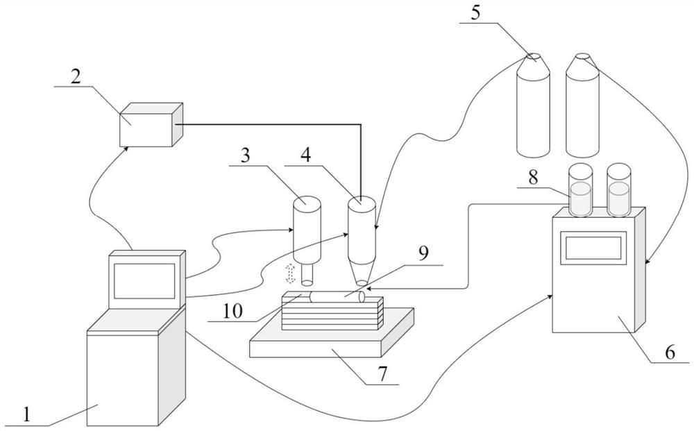
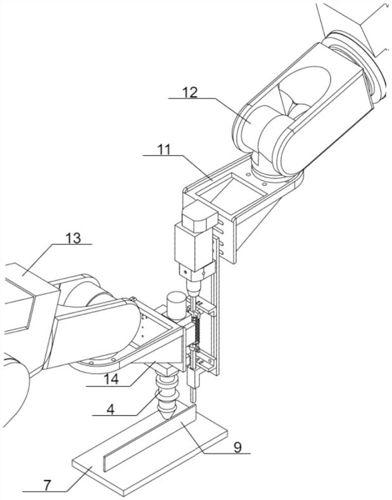
[0037]Taking continuous laser as the additive deposition heat source, 316L stainless steel powder as the additive metal material, and the substrate as 316L stainless steel, using unidirectional scanning to additively manufacture 316L stainless steel thin-walled parts as an example. The heat source of laser deposition manufacturing is FCL2000 fiber laser, the laser deposition head adopts FWC300 laser processing head, the feeding equipment adopts RC-PGF intelligent powder feeder, the controllers are YRC 1000 and DX200 control cabinets, and the motion actuators are GP 180 and MH 12 models respectively The robot arm, the power source of synchronous hammering is TE 3-CL electric hammer, which specifically includes the following steps:

[0038] Step 1: Sand the surface of the 316L stainless steel substrate, wipe it with absorbent cotton dipped in absolute ethanol to remove surfac...


PUM


Abstract

The invention discloses a synchronous hammering shape control device and method for metal component additive manufacturing. The device comprises a control device body, an additive deposition device, a synchronous hammering device, a clamping device and a moving device. The device is characterized in that the synchronous hammering device is installed on a synchronous hammering moving device through the clamping device and keeps synchronous hammering movement with an additive deposition head. The method is characterized in that the synchronous hammering moving device and the additive deposition head keep synchronous hammering movement. The device and the method have the beneficial effects that a solidification structure of an additive manufacturing metal component can be obviously refined, air hole and crack defects of the additive manufacturing metal component can be obviously improved, the residual stress of the additive manufacturing technical component can be obviously eliminated, deformation generated in the forming process of the additive manufacturing metal component can be controlled, the density of the additive manufacturing metal component can be improved, pollution is avoided, and the process application range is wide.

Description

technical field [0001] The invention belongs to the field of additive manufacturing, and in particular relates to a shape control device and method for additively manufactured metal components. Background technique [0002] Additive manufacturing technology is a digital manufacturing technology that accumulates materials layer by layer. At present, one of the main reasons that restricts the development of additive manufacturing metal component technology is that the grain growth of additive manufacturing metal components has obvious directionality, resulting in various metal components. Anisotropy; the microstructure of metal components in additive manufacturing is coarse, which reduces the mechanical properties of metal components; the process of additive manufacturing is an interlayer accumulation process, which will produce microstructural defects such as pores, cracks, and incomplete fusion, which will reduce the fatigue performance of metal components. [0003] At prese...

Claims


Application Information

Patent Timeline
Patent Type & Authority Applications(China)
IPC IPC(8): B22F12/00B22F10/28B22F10/31B22F12/90B22F10/50B22F10/18B33Y30/00B33Y40/00B33Y50/02
CPCB22F3/003B33Y30/00B33Y40/00B33Y50/02Y02P10/25
Inventor 吴东江于成水蔡昕彤牛方勇马广义
Owner DALIAN UNIV OF TECH
Why Eureka
Try Eureka