Polishing equipment for anticorrosive wood processing
A technology for anti-corrosion wood and equipment, used in metal processing equipment, grinding/polishing equipment, grinders, etc., can solve the problems of low work efficiency, laborious, easy to generate a large amount of dust, etc., to achieve high work efficiency and avoid offset effect.
- Summary
- Abstract
- Description
- Claims
- Application Information
AI Technical Summary
Problems solved by technology
Method used
Image

Examples
Embodiment 1
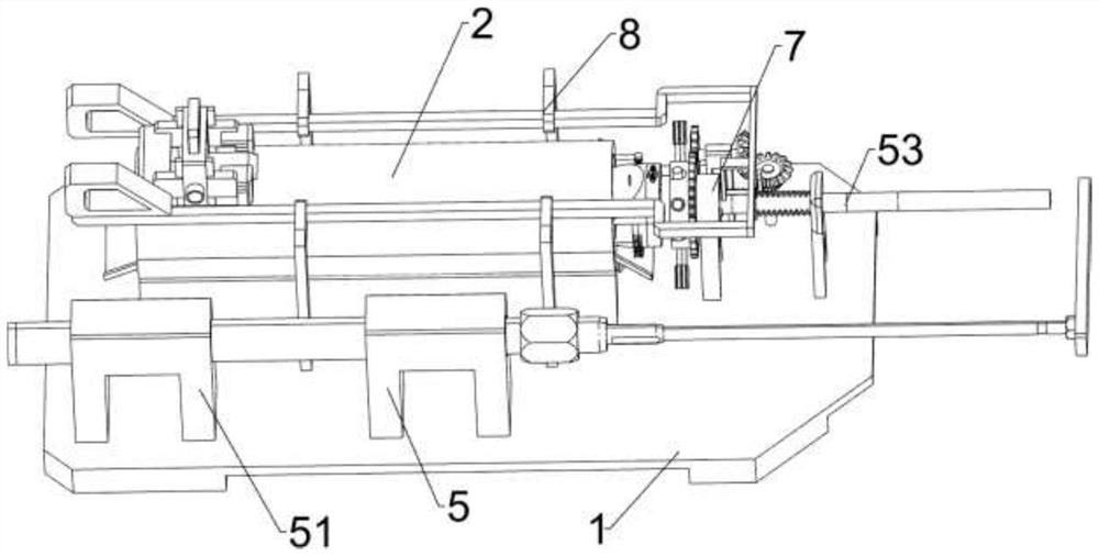
[0029] A grinding equipment for preservative wood processing, such as figure 1 , figure 2 , image 3 and Figure 6 As shown, it includes a base 1, a shell 2, a support plate 3, a grinder 4, a transmission device 5 and a clamping device 6. The top left rear part of the base 1 is fixedly connected to the shell 2, and the left part of the shell 2 is slidingly provided with a support The plate 3 is provided with a sander 4 in the middle of the support plate 3 , the base 1 is provided with a transmission device 5 , and the transmission device 5 is provided with a clamping device 6 .
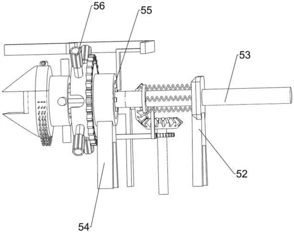
[0030] The transmission device 5 includes a cylinder 51, a first fixed block 52, a push rod 53, a support leg 54, a special-shaped hollow cylinder 55, an adjustment handle 56, a special-shaped block 57, a first spring 58 and a second fixed block 510, and a base 1. A cylinder 51 is fixedly connected to the front side of the top, and a first fixed block 52 is fixedly connected to the middle part of ...
Embodiment 2
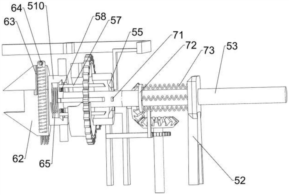
[0034] On the basis of Example 1, such as figure 1 , image 3 , Figure 4 and Figure 5 As shown, a rotating device 7 is also included, and the rotating device 7 includes a contact block 71, a sliding ring 72, a third spring 73, a special-shaped block 74, a ratchet bar 75, a first rotating shaft 76, a first ratchet 77, a first cone Gear 78, support frame 79, the second rotating shaft 710, the second bevel gear 711, missing gear 712 and full gear 713, push rod 53 left part circumferential intervals are provided with contact block 71, and push rod 53 left part circumferential sliding type design Sliding ring 72 is arranged, and the third spring 73 is evenly spaced between the right side of sliding ring 72 and the upper left side of first fixed block 52, and special-shaped block 74 is affixed to the rear side of sliding ring 72, and the outer rear side of special-shaped block 74 A ratchet bar 75 is affixed, and the base 1 is provided with a first rotating shaft 76 which is rot...
Embodiment 3
[0039] On the basis of embodiment 1 and embodiment 2, such as Figure 4 , Figure 6 , Figure 7 , Figure 8 and Figure 9 As shown, a reinforcement device 9 is also included. The reinforcement device 9 includes a fixed plate 91, a splint 92 and a fourth spring 94. The front and rear sides of the housing 2 are fixedly connected with a fixed plate 91, and the internal space of the fixed plate 91 is slidingly provided with The splint 92 has a fourth spring 94 fixedly connected between the inner surface of the splint 92 and the inner surface of the fixing plate 91 .
[0040] Also includes a cleaning device 10, the cleaning device 10 includes a first hair brush 101, a second hair brush 102, a second ratchet 103, a ratchet bar 104, a push block 105 and a lock 106, and the lower part of the outer surface of the fixed clamp block 62 is affixed There is a first hair brush 101, a second hair brush 102 is provided on the rear side of the right part of the housing 2 in a rotating mann...
PUM
 Abstract
Description
Claims
Application Information
 - Generate Ideas
- Intellectual Property
- Life Sciences
- Materials
- Tech Scout
- Unparalleled Data Quality
- Higher Quality Content
- 60% Fewer Hallucinations
Browse by: Latest US Patents, China's latest patents, Technical Efficacy Thesaurus, Application Domain, Technology Topic, Popular Technical Reports.
© 2025 PatSnap. All rights reserved.Legal|Privacy policy|Modern Slavery Act Transparency Statement|Sitemap|About US| Contact US: help@patsnap.com