Duplex medical oxygen bottle carrier

A technology for oxygen cylinders and trucks, applied in the field of trucks, which can solve problems such as no stress point, scratching noise, high-pressure oxygen explosion, etc., to facilitate operation and force application, prevent combustion and explosion, and increase friction coefficient Effect

Inactive Publication Date: 2021-07-23
王水龙
View PDF1 Cites 0 Cited by
  • Summary
  • Abstract
  • Description
  • Claims
  • Application Information

AI Technical Summary

Problems solved by technology

[0002] Oxygen cylinders are frequently used and very important medical equipment in hospitals. They are mainly used for respiratory diseases caused by hypoxia (such as asthma, bronchitis, pulmonary heart disease, etc.), heart and cerebrovascular diseases (such as: Coronary heart disease, myocardial infarction, cerebral hemorrhage, cerebral infarction) to relieve the symptoms of hypoxia; it can also be used for health care oxygen inhalation or rapid relief of fatigue after intense mental work and physical work, etc.; oxygen cylinders are generally erected during oxygen delivery In the ward, because the oxygen cylinder is thin and tall, its stability is poor. If it is accidentally touched, it is easy to fall over. Once it falls over, the patient will be very dangerous. Moreover, the oxygen cylinder is heavy and needs to be moved out and replaced with a new one after use. Oxygen bottle, the body of the bottle is a smooth cylinder, there is no stress point, and it is not easy to carry
[0003] Oxygen cylinders are high-pressure containers for storing and transporting oxygen. Generally, they are cylindrical airtight cylinders made of alloy structural steel by stamping and welding. After the cylinder is filled with high-pressure oxygen, the overall weight is relatively large, and it can be moved by two people at short distances. The staff lifts up and moves, but it is more dangerous and poses a greater threat to the personal safety of surrounding personnel; longer-distance transportation will be realized by oxygen cylinder trucks, which usually include slender vehicles The lower end of the car body has a supporting plate, and the lower part of the car body is provided with rollers. When carrying the oxygen cylinder, adjust the car body to a vertical state. One worker lifts the bottom side of the oxygen cylinder off the ground first, and the other Personnel push the car body so that the supporting plate extends between the bottom surface of the oxygen cylinder and the ground, then release the oxygen cylinder, the bottom of the oxygen cylinder is located on the supporting plate, and fix the tank body on the main body of the truck with straps Then pull the upper end of the car body backward to make the car body tilt backward, and finally push the car body to transfer the oxygen cylinder. This method requires the cooperation of two people to complete, and it is time-consuming and laborious, and the efficiency is low
[0004] The invention patent with the publication number CN107600130A discloses a medical oxygen cylinder carrier. In order to make the push plate push the oxygen cylinder forward, it is necessary to press the supporting plate against the ground and tilt the body of the carrier forward, so that it can be driven by a bevel gear. The transmission of the rod pushes the push plate forward. After the push plate pushes the oxygen cylinder to tilt forward and creates a gap with the ground, it pushes the truck body forward, inserts the supporting plate into the lower side of the oxygen cylinder, and tilts the truck body backward, thus Complete the loading of the oxygen cylinder, but it has the following defects technically: ①The oxygen cylinder is a slender cylinder, and when the push plate pushes the oxygen cylinder to tilt forward, it is easy to make the center of gravity of the oxygen cylinder move forward and exceed the range of the bottom of the cylinder, thus If the oxygen cylinder is driven forward by the protective belt, it will not only easily injure the personnel, but also the high-pressure oxygen in the cylinder may explode due to a large vibration, resulting in a greater safety accident; ②The floor of the ward is usually brushed Waterproof and non-slip coating, and when the truck body is pushed forward, the supporting plate is always pressed against the ground, which will not only scratch the ground coating, but also generate scratching noise, which is detrimental to the recovery of the patient; ③The structure is unreasonable, Only by tilting the truck body forward can the push plate extend forward and push the oxygen cylinder to tilt forward. When the pallet is about to be inserted into the lower end of the oxygen cylinder, if the oxygen cylinder has not tilted forward, the pallet cannot be inserted into the lower end of the oxygen cylinder; If the oxygen cylinder has been tilted forward, continue to move forward to insert the support plate into the lower end of the oxygen cylinder, the oxygen cylinder will continue to tilt forward, so that the oxygen cylinder will fall forward, causing a safety accident. Such a structure is unreasonable ;④The operation is very difficult. During the process of loading the oxygen cylinder, the operator must not only control the proper angle of the forward tilt of the truck body, but also push the truck forward to insert the pallet into the lower end of the oxygen cylinder; If the angle of inclination is too small, the gap between the oxygen cylinder and the ground is not enough to be inserted into the pallet, and if the forward tilt angle of the transport vehicle is too large, the oxygen cylinder will fall forward, making it difficult to unload the oxygen cylinder.

Method used


Image

  • Duplex medical oxygen bottle carrier
  • Duplex medical oxygen bottle carrier
  • Duplex medical oxygen bottle carrier

Examples


Embodiment Construction

[0045] The present invention will be further described below in conjunction with specific embodiments. The exemplary embodiments and descriptions of the present invention are used to explain the present invention, but not as a limitation to the present invention.

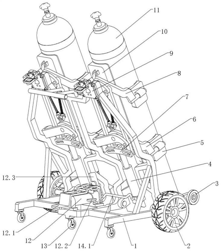
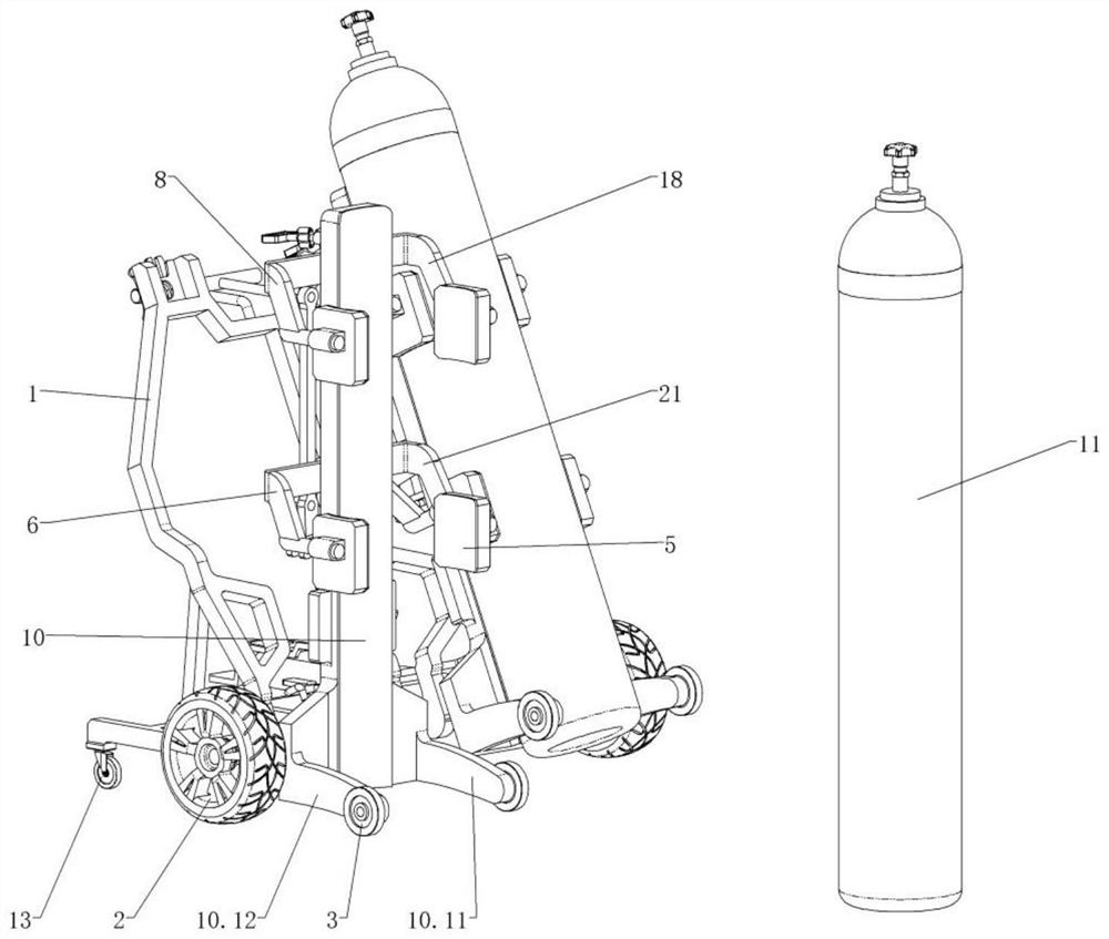
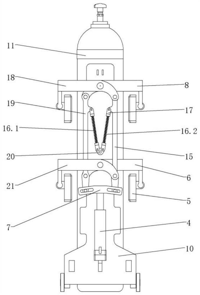
[0046] Such as figure 1 , figure 2 As shown, a dual medical oxygen cylinder transport vehicle includes a frame mechanism, a first clamping mechanism, a second clamping mechanism, and a locking mechanism. It is characterized in that: the frame mechanism includes a vehicle frame 1, wheels 2, front Support wheel 3, hydraulic pump 12, universal caster 13, first hydraulic pipe 14.1, second hydraulic pipe 14.2; the first clamping mechanism includes hydraulic cylinder 4, splint 5, fourth arm 6, transverse groove rod 7, second Arm 8, flip frame 10, second link 15, first spring 16.1, second spring 16.2, spring terminal 17, first arm 18, first link 19, fixed terminal 20, third arm 21, swing bar 22 , the pull ring rod 23, t...


PUM


Abstract

The invention discloses a duplex medical oxygen bottle carrier. Two wheels are installed on the two sides of a frame, three universal trundles are installed on the rear side of the frame, the front ends of four arms in each clamping mechanism are each provided with a clamping plate, the rear sides of the four arms in each clamping mechanism are rotationally connected with a turnover frame, a first connecting rod is rotationally connected with a second arm and a fourth arm, and a second connecting rod is rotationally connected with a third arm and a fourth arm. The second connecting rod is rotationally connected with the first arm and the third arm, the two clamping mechanisms are rotationally connected with the frame, the hydraulic pump communicates with the two hydraulic cylinders, the hydraulic cylinders can stretch by treading a pedal, a transverse groove rod drives the first connecting rod and the second connecting rod to move upwards, and therefore four clamping plates clamp the oxygen bottle; a pressure release valve is treaded to relieve thrust of a hydraulic cylinder, a first spring and a second spring pull a first connecting rod and a second connecting rod downwards, four clamping plates release clamping of the oxygen bottle, a clamping mechanism swings forwards to enable a front supporting wheel to make contact with the ground, and the process of clamping and releasing the oxygen bottle is achieved. After the clamping mechanism swings backwards and is locked, the oxygen bottle can be transferred.

Description

technical field [0001] The invention relates to the field of transport vehicles, in particular to a dual-connected medical oxygen cylinder transport vehicle. Background technique [0002] Oxygen cylinders are frequently used and very important medical equipment in hospitals. They are mainly used for respiratory diseases caused by hypoxia (such as asthma, bronchitis, pulmonary heart disease, etc.), heart and cerebrovascular diseases (such as: Coronary heart disease, myocardial infarction, cerebral hemorrhage, cerebral infarction) to relieve the symptoms of hypoxia; it can also be used for health care oxygen inhalation or rapid relief of fatigue after intense mental work and physical work, etc.; oxygen cylinders are generally erected during oxygen delivery In the ward, because the oxygen cylinder is thin and tall, its stability is poor. If it is accidentally touched, it is easy to fall over. Once it falls over, the patient will be very dangerous. Moreover, the oxygen cylinder ...

Claims


Application Information

Patent Timeline
Patent Type & Authority Applications(China)
IPC IPC(8): B62B3/04B62B3/02B62B3/10B62B5/00
CPCB62B3/02B62B3/04B62B3/104B62B5/00B62B2202/022B62B2203/70
Inventor 王水龙
Owner 王水龙
Why Eureka
Try Eureka