Device capable of automatically rotating and switching multiple paths of signals and implementation method

A multi-channel signal, main body technology, applied in the direction of measuring device, measuring device casing, electrical measuring instrument parts, etc., can solve the problems of signal distortion, loss, large size, etc., to improve work stability, save development costs, Easy and fast effect

Pending Publication Date: 2021-07-23
天津七一二移动通信有限公司
View PDF0 Cites 0 Cited by
  • Summary
  • Abstract
  • Description
  • Claims
  • Application Information

AI Technical Summary

Problems solved by technology

In order to switch between different stations, it is necessary to design circuit boards, solder various components, and integrate multiple relay boards into one piece. Considering the interference of components during work, they need to be isolated from each other and have a large volume; the traditional implementation method requires Sending switching instructions to switch relays continuously requires programming; at the same time, the relays need to work continuously during the test process, which will generate large energy consumption and electromagnetic interference; influence, and sometimes cause signal distortion
In the traditional implementation method, each station cannot realize equal-length wiring, and the consistency of the test results of each station cannot be guaranteed; once the relay is stuck, damaged or the program is confused when the relay switches multiple signals, it is likely to switch the two signals at the same time to the same road, resulting in damage to the product under test and the test circuit, resulting in greater losses

Method used


Image

  • Device capable of automatically rotating and switching multiple paths of signals and implementation method
  • Device capable of automatically rotating and switching multiple paths of signals and implementation method
  • Device capable of automatically rotating and switching multiple paths of signals and implementation method

Examples


Embodiment Construction

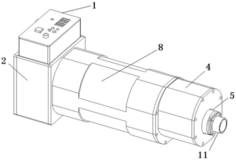
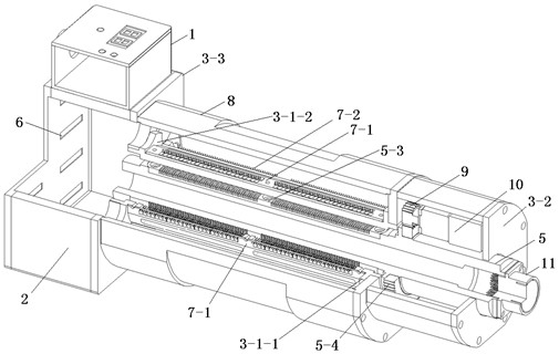
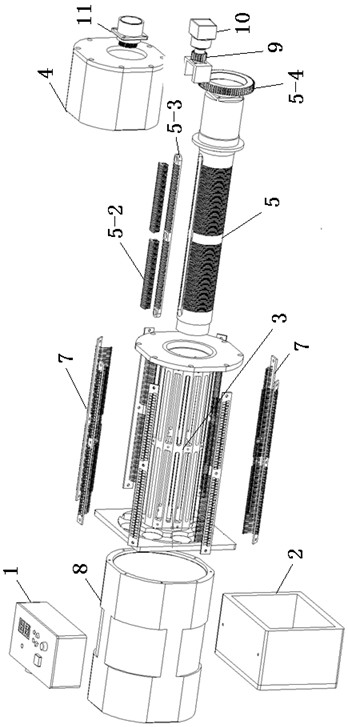
[0053] Such as Figure 1 to Figure 14 As shown, a device that can rotate and switch multiple signals autonomously, including a control box 1, a junction box 2, a fixed shaft 3, a drive box 4, a slip ring moving shaft 5, a micro-rectangular electrical connector 6, and a circuit board 7 , slip ring housing 8, gear pair 9, stepper motor 10, circular connector 11 and control circuit;

[0054] The fixed shaft 3 includes a circular cylinder 3-1, a connecting flange I3-2, a connecting flange II3-3, and a circle of convex disc I3-1-1 and convex disc II3-1 are arranged on both sides of the circular cylinder 3-1 -2. External threads are respectively provided on the outer cylinders of convex disk Ⅰ 3-1-1 and convex disk Ⅱ 3-1-2, and several semicircular grooves 3-1- are arranged at intervals on the circumferential surface of convex disk Ⅱ 3-1-2. 2-1, several circuit board areas 3-1-3 are arranged at intervals along the circumferential surface of the circular cylinder 3-1, and each circu...


PUM


Abstract

The implementation method of the device capable of automatically rotating and switching multiple paths of signals comprises the following steps: connecting the circular connector with external test equipment; connecting a plurality of micro-rectangular electric connectors with external products to be tested, wherein each micro-rectangular electric connector corresponds to one product to be tested to form a station 1 to a station N; selecting the number of a station 1 where a to-be-tested product is located through the station selection button, then enabling the single-chip microcomputer MCU to control the stepping motor to start to rotate after the OK button is pressed, and controlling the stepping motor to stop rotating when the stepping motor rotates to the set station, so that at the moment, a signal link formed by the test equipment, the circular connector, the micro-rectangular electric connector and the product to be tested is formed, and the test equipment completes the test of the product at the station 1; and testing the products from the station 2 to the station N in sequence according to the steps. The device is small in size and flexible to install and use, circuits are in one-to-one correspondence, and the troubleshooting complexity is low. The problem that an existing multi-station relay switching device is large in size is solved.

Description

technical field [0001] The invention relates to a device capable of autonomously rotating and switching multi-channel signals and a realization method, which are used for multi-station control and switching of measurement signals. Background technique [0002] The spin-type multi-channel signal switching device is mainly used in the environment of measurement and control equipment, etc., to switch and select multiple signals of multiple similar products that need to be tested, and to complete the physical connection between the test equipment and the signal of the product under test, so as to complete the test. Time-sharing test of various performance indicators of multiple tested products. [0003] In the traditional implementation methods, there are mainly relay circuit boards, etc., which mainly rely on the relay switch matrix to realize the switching of different stations. In order to switch between different stations, it is necessary to design circuit boards, solder va...

Claims


Application Information

Patent Timeline
Patent Type & Authority Applications(China)
IPC IPC(8): G01R31/00G01R1/04
CPCG01R1/0408G01R31/00
Inventor 叶宁常冠宇孟冬冬徐亚天郭旺邵远筝李胜男
Owner 天津七一二移动通信有限公司
Why Eureka
Try Eureka