Metal film and sputtering target

A metal film and sputtering target technology, which is applied in the field of sputtering targets, can solve problems such as the deterioration of electrical or optical properties of metal films, and achieve the effects of high-precision etching, inhibiting etching rate, and inhibiting agglutination

Pending Publication Date: 2021-07-23
MITSUBISHI MATERIALS CORP
View PDF11 Cites 0 Cited by
  • Summary
  • Abstract
  • Description
  • Claims
  • Application Information

AI Technical Summary

Problems solved by technology

[0018] In addition, in a metal film made of Ag or Ag alloy, Ag is easily aggregated by heat, so for example, aggregation protrusions (hillocks) caused by heating in the proce

Method used

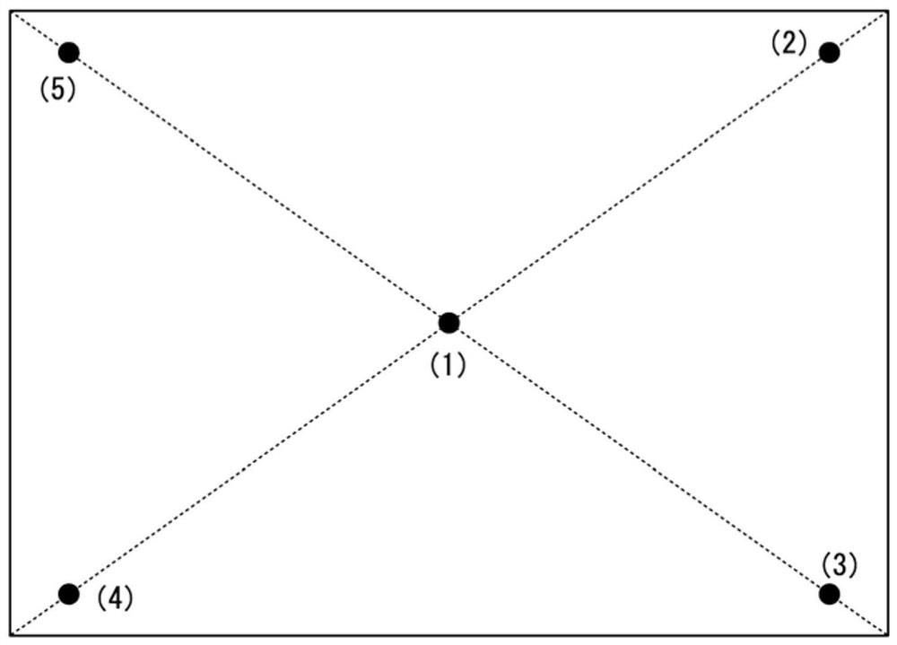
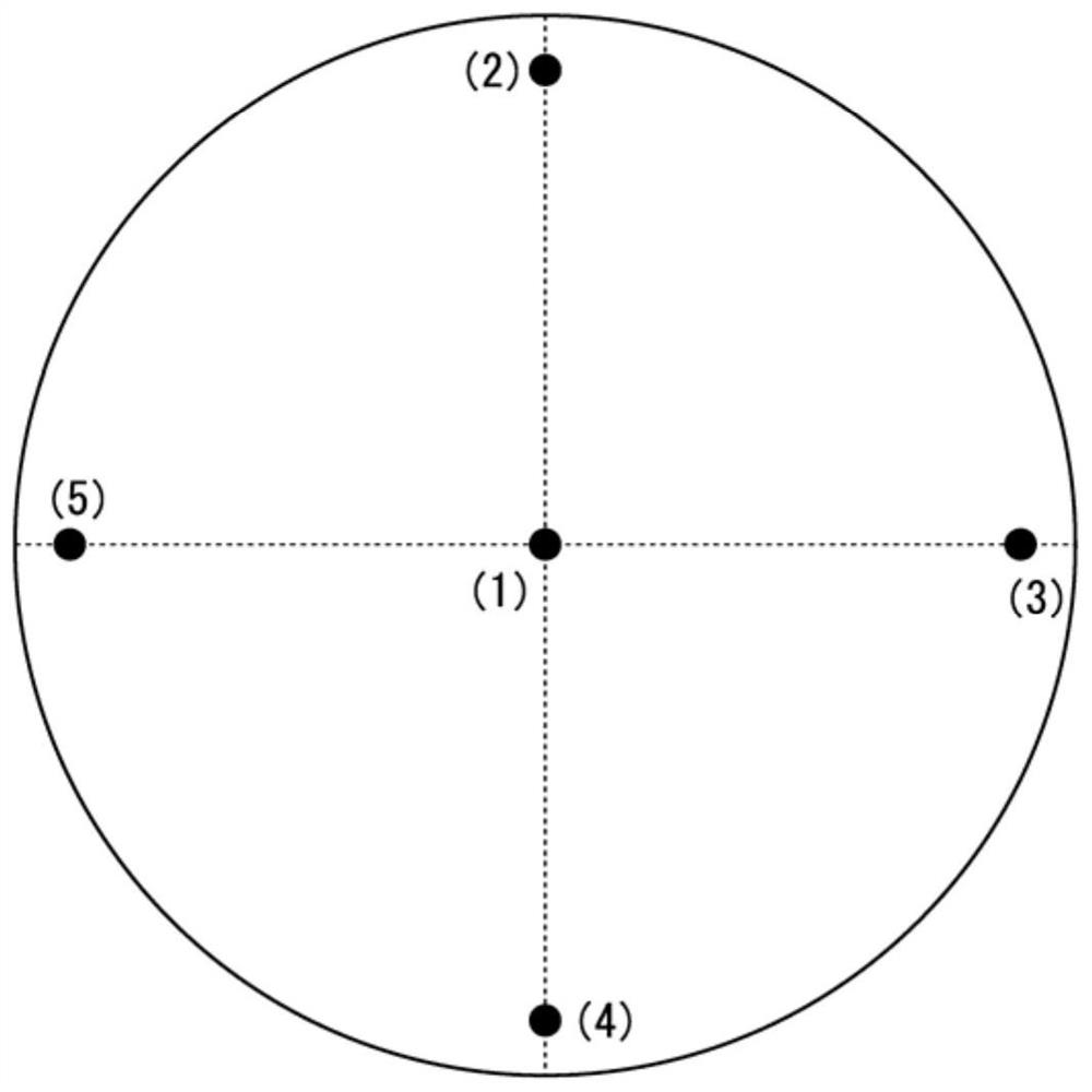
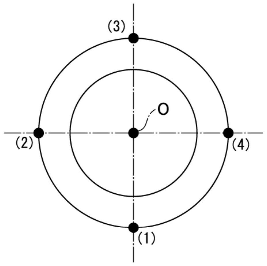

Image

  • Metal film and sputtering target
  • Metal film and sputtering target
  • Metal film and sputtering target

Examples


Embodiment

[0121] The results of confirmation experiments conducted to confirm the effectiveness of the present invention will be described below.

[0122] By repeated electrolytic refining and component analysis by ICP emission spectrometry, the Pd content was limited to 40 mass ppm or less, the Pt content was 20 mass ppm or less, the Au content was 20 mass ppm or less, and the Rh content was limited to 20 mass ppm or less. An Ag raw material whose total content of Pd, Pt, Au, and Rh is 50 mass ppm or less is 10 mass ppm or less. In addition, in Comparative Examples 3 to 8, an Ag raw material in which the content of the above-mentioned elements was not limited was used.

[0123] The Ag raw material is melted in a vacuum atmosphere and replaced with Ar gas, then a Cu raw material with a purity of 99.9% by mass or higher is added, and if necessary, a Sb raw material, a Zn raw material, a Sn raw material, a Pb raw material, and a Ti raw material are added with a purity of 99.9% by mass or ...


PUM

PropertyMeasurementUnit
Thicknessaaaaaaaaaa
Thicknessaaaaaaaaaa

Abstract

A metal film of the present invention contains Cu in a range of 0.10-5.00 at. %, not more than 40 mass ppm of Pd, not more than 20 mass ppm of Pt, not more than 20 mass ppm of Au, and not more than 10 mass ppm of Rh, the total contained amount of Pd, Pt, Au, and Rh being not more than 50 mass ppm, and the remaining portion being Ag and unavoidable impurities.

Description

technical field [0001] The present invention relates to, for example, a metal film used as a reflective film, an electrode film, or a wiring film, and a sputtering target used when forming the metal film. [0002] This application claims priority based on Patent Application No. 2018-228367 filed in Japan on December 5, 2018, and uses the content thereof here. Background technique [0003] For example, as a reflective film, an electrode film, and a wiring film of a display device such as a liquid crystal display, an organic EL display, or a touch panel, it has been proposed to use a metal film made of Ag or an Ag alloy as disclosed in Patent Document 1, for example. [0004] In addition, in Patent Documents 2 to 4, a laminated film having a laminated structure of a transparent conductive oxide film and a metal film made of Ag or an Ag alloy is applied. [0005] In the reflective film, the electrode film, and the wiring film described above, as shown in the above-mentioned Pa...

Claims


Application Information

Patent Timeline
IPC IPC(8): C23C14/14C22C5/06C23C14/34G02F1/1335G02F1/1343C22F1/00C22F1/14
CPCC22C5/06C22F1/14C23C14/3414C23C14/185H01J37/3429C22C5/08C22C1/03C22C1/02C23C14/14
Inventor 岁森悠人野中庄平小见山昌三林雄二郎
Owner MITSUBISHI MATERIALS CORP
Why Eureka
Try Eureka