Carbon dioxide gas suction and separation device and method of mixed working medium circulation system

A carbon dioxide, circulating system technology, applied in separation methods, chemical instruments and methods, steam engine installations, etc., can solve the problems of not meeting storage requirements and high energy consumption, and achieve the improvement of ejection ratio and work efficiency, and reduction of energy consumption and lower energy consumption. The effect of emissions

Pending Publication Date: 2021-07-27
XI AN JIAOTONG UNIV
View PDF9 Cites 1 Cited by
  • Summary
  • Abstract
  • Description
  • Claims
  • Application Information

AI Technical Summary

Problems solved by technology

The carbon dioxide component in the mixed working medium of the supercritical water gasification power generation cycle accounts for 8%-10%, which is much higher than the content of carbon dioxide gas in the conventional steam Rankine cycle. Meet storage requirements after carbon dioxide gas separation

Method used


Image

  • Carbon dioxide gas suction and separation device and method of mixed working medium circulation system

Examples


Embodiment 1

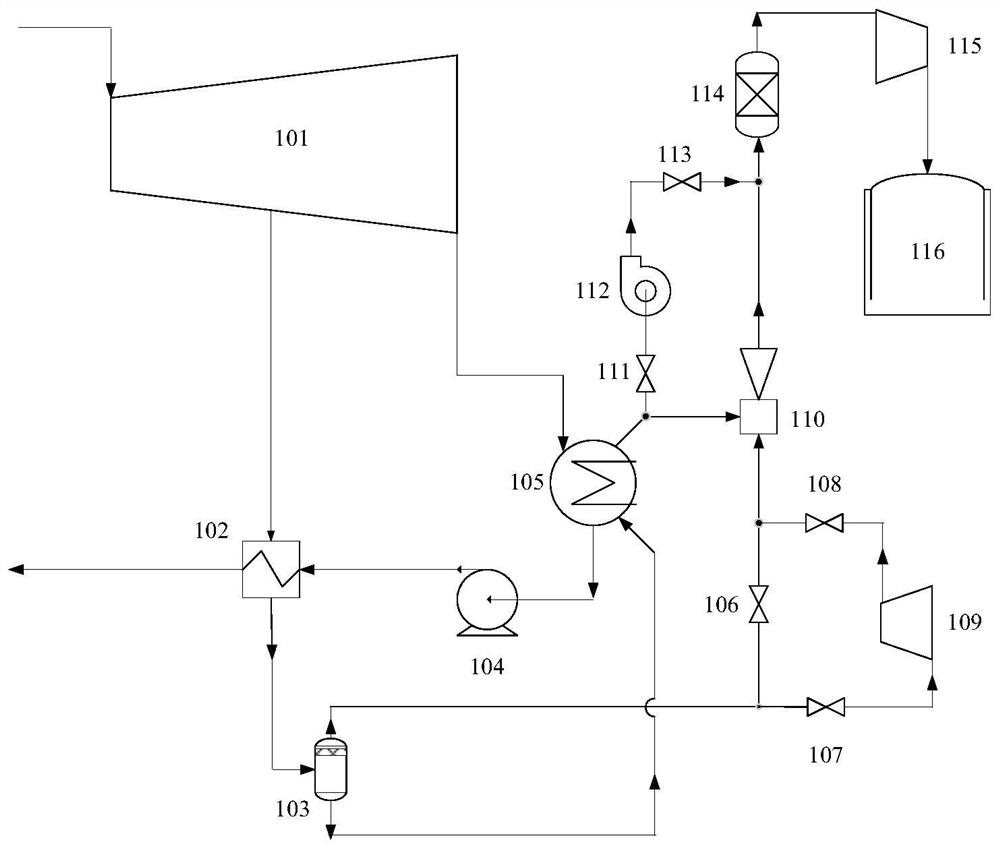
[0039] A carbon dioxide gas suction and separation device for a mixed working medium circulation system according to an embodiment of the present invention, the steam extraction outlet of the steam turbine 101 is connected to the hot fluid inlet of the feed water heater 102, the outlet of the steam turbine 101 is connected to the inlet of the condenser 105, and the condensate pump The inlet of 104 is connected to the liquid outlet of condenser 105, the cold fluid inlet of feed water heater 102 is connected to the outlet of condensate water pump 104, the inlet of gas-liquid separator 103 is connected to the outlet of hot fluid of feed water heater 102, the liquid outlet of gas-liquid separator 103 is connected to the outlet of condensate pump 104 The inlet of the vaporizer 105 is connected, the high-pressure inlet of the ejector 110 is connected with the outlet of the gas-liquid separator 103, the low-pressure inlet of the ejector 110 is connected with the gas outlet of the conde...

Embodiment 2

[0042] In this embodiment of the present invention, the difference from Embodiment 1 is that a centrifugal compressor is connected in series before the high-pressure inlet of the ejector. When the suction device is working, open the centrifugal first inlet valve and the centrifugal first outlet valve, and close the bypass valve. The centrifugal compressor increases the gas pressure at the outlet of the gas-liquid separator to 1500kPa, the injection coefficient of the ejector can be increased by 35%, and the suction flow rate of the ejector to the carbon dioxide in the condenser can be increased by 14%.

[0043] In embodiment 1, the compressor and the inlet and outlet valves of the compressor are closed, and the bypass valve is in an open state. When the steam extraction pressure of the steam turbine is high, no additional power consumption is required to achieve the purpose of energy saving; in embodiment 2, the compressor and the compressor The inlet and outlet valves are ope...

Embodiment 3

[0046] The difference from Embodiment 1 is that a centrifugal compressor is connected in series before the high-pressure inlet of the ejector, and a centrifugal fan is connected in parallel between the low-pressure inlet and the outlet of the ejector. When the suction device is working, open the first inlet valve and the first outlet valve, close the bypass valve, and open the inlet and outlet valves of the centrifugal fan at the same time. The centrifugal compressor increases the gas pressure at the outlet of the gas-liquid separator to 1500kPa, the injection coefficient of the ejector can be increased by 35%, and the suction flow rate of the ejector to the carbon dioxide in the condenser can be increased by 14%. Utilizing the auxiliary suction effect of the centrifugal fan, the suction flow rate of the suction device for the carbon dioxide in the condenser can be further increased by 30%.

[0047] According to the above-mentioned embodiments of the present invention, the cen...


PUM


Abstract

The invention discloses a carbon dioxide gas suction and separation device and method of a mixed working medium circulation system. The carbon dioxide gas suction and separation device comprises a condenser, a feed water heater, a gas-liquid separator and an ejector; a first inlet of the condenser is in communication with an outlet of a steam turbine; the feed water heater is provided with a hot fluid inlet, a hot fluid outlet, a cold fluid inlet and a cold fluid outlet; the hot fluid inlet is used for being in communication with a middle steam extraction outlet of the steam turbine, and the cold fluid inlet is in communication with a liquid outlet of the condenser; an inlet of the gas-liquid separator is in communication with the hot fluid outlet, and a liquid outlet of the gas-liquid separator is in communication with a second inlet of the condenser; and a high-pressure inlet of the ejector is in communication with a gas outlet of the gas-liquid separator, and a low-pressure inlet of the ejector is in communication with a gas outlet of the condenser. According to the carbon dioxide gas suction and separation device and method, efficient separation of water vapor and carbon dioxide in the mixed working medium can be achieved, and energy consumption inthe gas separation process can be reduced.

Description

technical field [0001] The invention belongs to the technical field of power generation equipment and relates to the field of carbon dioxide gas suction and separation, in particular to a carbon dioxide gas suction and separation device and method for a mixed working fluid circulation system. Background technique [0002] For a long time, coal is the main source of energy, and other forms of energy are supplementary supply methods; extensive coal utilization will lead to low energy utilization efficiency and the release of CO 2 , SOx, NOx, Ag, As and a large amount of dust have caused serious environmental pollution, which does not meet the basic requirements of long-term energy security. The development of clean and efficient coal utilization has become the primary task of China's energy transformation. [0003] Supercritical coal gasification power generation technology uses supercritical water as the reaction medium, which can realize coal thermal decomposition, gasificat...

Claims


Application Information

Patent Timeline
Patent Type & Authority Applications(China)
IPC IPC(8): F28B5/00F28B9/00F28B9/10B01D53/26F01K13/00F01D15/10F01K7/32
CPCF28B5/00F28B9/00F28B9/10B01D53/265F01K13/00F01D15/10F01K7/32
Inventor 戴义平范刚
Owner XI AN JIAOTONG UNIV
Why Eureka
Try Eureka