
Low-profile miniaturized decoupling structure based on patch MIMO antenna

A patch antenna and low-profile technology, which is applied in the antenna grounding switch structure connection, antenna coupling, antenna, etc., can solve the problems of low profile, unfavorable promotion and use of patch MIMO antennas, and difficult to compact structure, so as to achieve compact structure and efficient Conducive to integrated design and miniaturization

Active Publication Date: 2021-07-27
NANJING UNIV OF SCI & TECH
View PDF4 Cites 3 Cited by
  • Summary
  • Abstract
  • Description
  • Claims
  • Application Information

AI Technical Summary

Problems solved by technology

[0007] In short, the problem existing in the existing technology is that it is difficult to meet the requirements of compact structure and low profile while the decoupling structure of the patch MIMO antenna achieves good performance, which is not conducive to the popularization and use of the patch MIMO antenna in practical applications.

Method used


Image

  • Low-profile miniaturized decoupling structure based on patch MIMO antenna
  • Low-profile miniaturized decoupling structure based on patch MIMO antenna
  • Low-profile miniaturized decoupling structure based on patch MIMO antenna

Examples


Embodiment Construction

[0024] In order to make the purpose, technical solution and advantages of the present application clearer, the present application will be further described in detail below in conjunction with the accompanying drawings and embodiments. It should be understood that the specific embodiments described here are only used to explain the present application, and are not intended to limit the present application.

[0025] It should be noted that if there is a directional indication (such as up, down, left, right, front, back...) in the embodiment of the present invention, the directional indication is only used to explain the position in a certain posture (as shown in the accompanying drawing). If the specific posture changes, the directional indication will also change accordingly.

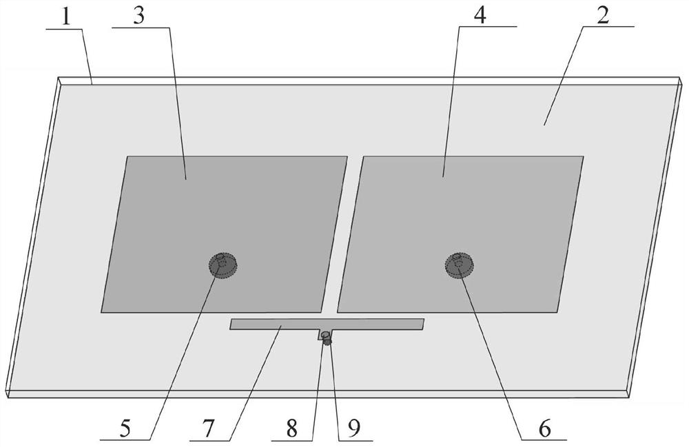
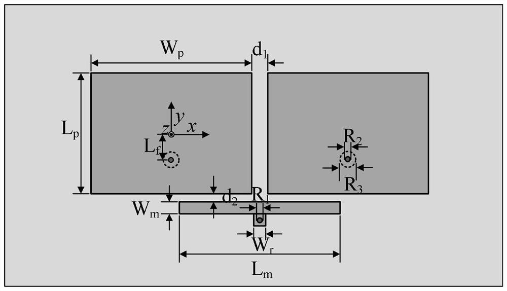
[0026] In one embodiment, combined with figure 1 and figure 2 , provides a low-profile miniaturized decoupling structure based on a patch MIMO antenna, the decoupling structure includes a metal groun...


PUM


Abstract

The invention discloses a low-profile miniaturized decoupling structure based on a patch MIMO antenna, and the decoupling structure comprises a metal grounding plate and a rectangular dielectric substrate which are sequentially arranged from bottom to top, and the upper surface of the rectangular dielectric substrate is provided with a first patch antenna, a second patch antenna and a microstrip resonator. The distances from the coupling edges of the antennas and the microstrip resonator to the microstrip resonator are equal, and the coupling strengths are equal; the first patch antenna and the second patch antenna are respectively provided with a first input port and a second input port, one side of the central position of the microstrip resonator is provided with a square branch knot, and the center of the square branch knot is provided with a metalized via hole; and the coupling from the first patch antenna to the second patch antenna and the coupling from the first patch antenna to the second patch antenna after passing through the microstrip resonator are in equal amplitude and opposite directions. The structure has the advantages of being compact in structure, low in profile, high in performance and the like, and is suitable for an MIMO communication system.

Description

technical field [0001] The invention belongs to the technical field of microwave passive devices, in particular to a low-profile miniaturized decoupling structure based on patch MIMO antennas. Background technique [0002] In the design of a MIMO antenna system, multiple antenna units are usually arranged in a limited space, and the strong mutual coupling between adjacent antenna units forms a large electromagnetic interference, which affects the performance of the MIMO system. On the other hand, the patch antenna is one of the most typical antenna forms in MIMO systems due to its low profile, easy integration and diverse performance. In order to make full use of the advantages of the patch antenna, it is of great application value to design a compact, low-profile, high-performance patch antenna decoupling structure. [0003] In recent years, researchers have studied a variety of decoupling structure design methods. [0004] In Literature 1 (K.-L.Wu, C.Wei, X.Mei, and Z.-Y...

Claims


Application Information

Patent Timeline
Patent Type & Authority Applications(China)
IPC IPC(8): H01Q1/38H01Q1/48H01Q1/50H01Q1/52H01Q9/04H01Q21/06
CPCH01Q1/38H01Q1/50H01Q1/48H01Q1/521H01Q9/0407H01Q21/065
Inventor 裴天齐祝雷王建朋吴文
Owner NANJING UNIV OF SCI & TECH
Learn More