
A phase-locked loop circuit and its control method, semiconductor device and electronic equipment

A phase-locked loop and circuit technology, applied in the direction of electrical components, automatic power control, etc., can solve problems such as system digital algorithm errors, delay chain abnormal duty cycle or glitches, etc.

Active Publication Date: 2022-04-01
COMNAV TECH
View PDF0 Cites 0 Cited by
  • Summary
  • Abstract
  • Description
  • Claims
  • Application Information

AI Technical Summary

Problems solved by technology

When there is only waveform alignment, the frequency of the output signal and the input signal are not in multiples, and the digital algorithm finds that the output frequency of the delay chain is too different from the demand value, then configure the delay unit delay of the delay chain to the minimum, and let the delay chain lock again. But this will cause abnormal duty cycle or glitch in the delay chain, when the output of the delay-locked loop circuit is used for the system clock, it may cause errors in the system digital algorithm

Method used


Image

  • A phase-locked loop circuit and its control method, semiconductor device and electronic equipment
  • A phase-locked loop circuit and its control method, semiconductor device and electronic equipment
  • A phase-locked loop circuit and its control method, semiconductor device and electronic equipment

Examples


Embodiment Construction

[0019] The following description is made to illustrate the general principles of the invention and is not meant to limit the inventive concepts claimed herein. Furthermore, certain features described herein can be used in combination with other described features in each of the various possible combinations and permutations.

[0020] Unless otherwise specifically defined herein, all terms are to be given their broadest interpretations, including meanings implied in this specification and meanings understood by those skilled in the art and / or as defined in dictionaries, treatises, and the like. In order to describe the technical content, structural features, achieved goals and effects of the present invention in detail, the following will be described in detail in conjunction with the embodiments and accompanying drawings.

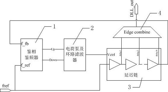
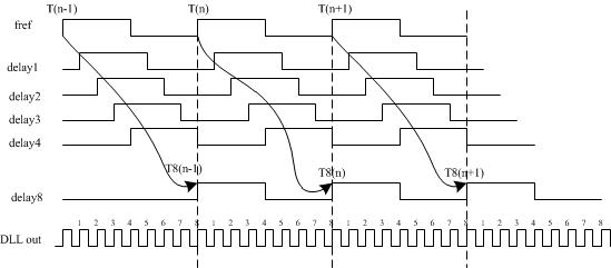
[0021] see figure 1 , figure 1 It is a circuit structure diagram of a delay-locked loop in the prior art, including a phase-frequency detector (or freque...


PUM


Abstract

The embodiment of the present invention discloses a phase-locked loop circuit, including: a phase frequency comparison unit, which compares the phase of the external reference clock signal with the phase of the comparison clock signal, and generates an error signal corresponding to the comparison result; an oscillation unit, which generates the oscillation frequency An internal clock signal corresponding to the error signal; a frequency division unit, which divides the frequency of the internal clock signal with a preset frequency division ratio to generate the comparison clock signal; a control unit, which divides the phase of the external reference clock signal After comparing with the phase of the comparison clock signal, a control signal for respectively changing the circuit connection between the oscillation unit and the frequency division unit is generated. The phase-locked loop circuit provided by the embodiment of the present invention can automatically detect the locking of the phase-locked loop circuit and correct the wrong locking and harmonic locking of the phase-locking loop circuit. When it is wrongly locked, it does not need to be reset again to ensure that the phase of its output does not change abruptly, nor does it generate additional spike signals, which will affect the integrity of the clock signal.

Description

technical field [0001] The invention relates to the technical field of semiconductors, in particular to a phase-locked loop circuit and its control method, a semiconductor device and electronic equipment including the phase-locked loop circuit. Background technique [0002] Between the stand-alone machines of the data communication system, it is often necessary to transmit the clock, and perform frequency multiplication or frequency division processing on the clock. Since the jitter index of the transmission clock is not ideal, the traditional method is to use a hardware phase-locked loop (PLL: Phase Locked Loop) circuit to implement clock loop tracking, or use a delay phase-locked loop circuit (DLL: delay locked loop). A delay-locked loop circuit is a circuit that can output a periodic signal that has the same period as the input clock signal and has a certain time delay. [0003] The core component of the delay-locked loop is the voltage-controlled delay line (VCDL: volta...

Claims


Application Information

Patent Timeline
Patent Type & Authority Patents(China)
IPC IPC(8): H03L7/091
CPCH03L7/091H03L7/0816H03L7/0995H03L2207/14H03L7/0812H03L7/0891
Inventor 刘杰
Owner COMNAV TECH
Learn More