

Solidifiable spacer fluid
A technology of spacer fluid and diatomaceous earth, applied in the direction of chemical instruments and methods, drilling compositions, etc., can solve problems such as not given
- Summary
- Abstract
- Description
- Claims
- Application Information
AI Technical Summary
Problems solved by technology
Method used
Image

Examples
Embodiment 1
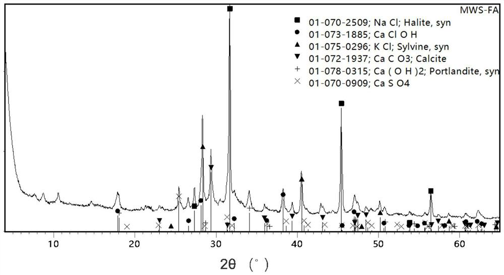
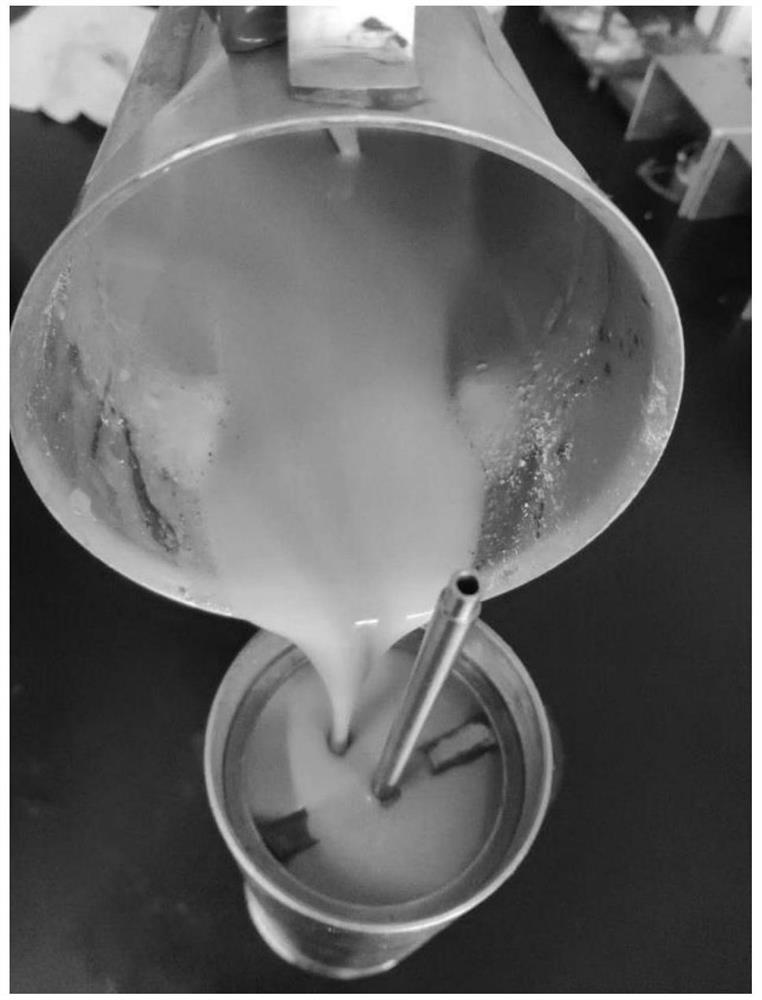
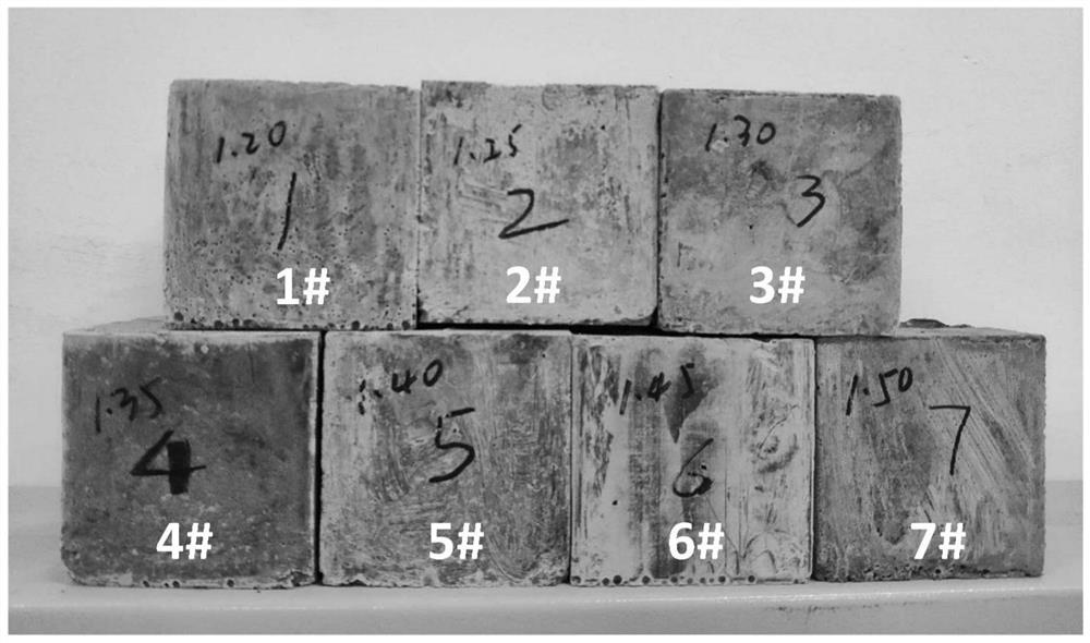
[0042]According to the formula shown in Table 2, at first by diatomite, slag in the cementitious material, fly ash in the cementitious material, activator (fly ash), soil suspending agent (sepiolite) and solid dehydration agent (PC-G86S) to obtain a dry mix of curable spacers, and then prepare curable spacers numbered 1# to 8# according to Table 2. Among them, the flow state of the curable spacer liquid numbered 2# poured into the slurry cup of the thickener is as follows: figure 2 shown. According to the API RP10B-2-2013 specification, the performance of each formula was tested, and the results are shown in Table 3.
[0043] Table 2
[0044]
[0045]
[0046] table 3
[0047]
[0048] The following conclusions can be obtained from Table 3: (1) In terms of slurry density, it is not possible to use expensive hollow glass microspheres as a lightening agent, and only by increasing the pulping rate can obtain 1.20g / cm 3 to 1.50g / cm 3 curable spacer fluid. (2) In te...
Embodiment 2
[0051] In Table 2 of Example 1, select the curable spacer fluid numbered 2#, add retarder H10L based on the weight of the solid component of the curable spacer fluid, and measure the thickening conditions as 27°C×20MPa, 47°C× The thickening curves at 20MPa, 67℃×30MPa and 87℃×35MPa are shown in Table 4. Partial thickening curves at 27°C, 47°C, 67°C and 87°C are selected, corresponding to Figure 4A , Figure 4B , Figure 4C and Figure 4D .
[0052] Table 4
[0053]
[0054] Remarks: The thickening time is the time required for the consistency to reach 30BC in the thickening curve.
[0055] From Table 4 and Figure 4A to Figure 4D It can be seen that by adjusting the amount of retarder, the curing of the curable spacer fluid at 27°C to 87°C can be controlled and adjustable, and the thickening curve has no abnormal phenomenon.
[0056] In addition, in Example 1, after changing the activator in the 1# formula into a commonly used activator in the building materials indu...
Embodiment 3
[0058] In Table 2 of Example 1, select the curable spacer fluid numbered as 2# to investigate the compatibility of the curable spacer fluid with drilling mud (numbered as M) and oil well cement slurry (numbered as C) respectively. The results are shown in Table 5.
[0059] The specific method is: (1) take samples according to the mixing ratio shown in Table 5, and mix them for 10 minutes at a stirring speed of 1000 rpm in a Waring mixer to obtain each mixed sample; Curing in a pressure curing instrument for 30 minutes, using a 6-speed viscometer to measure rheological readings; (3) Curing each mixed sample in a water bath at 60°C for 3 days to observe the curing status of each mixed sample or measure its strength. Among them, the drilling mud formula numbered M is "100% seawater + 0.2% NaOH + 0.2% NaOH 2 CO 3 +0.3% viscosifier PF-XCD+1.0% drilling soil+2.0%PF-Flotrol+0.2% coating agent PF-Plus+3.0%KCl+16% barite powder, % is weight percentage, slurry density is 1.20 g / cm 3...
PUM
| Property | Measurement | Unit |
|---|---|---|
| Density | aaaaa | aaaaa |
Abstract
Description
Claims
Application Information