
A combined luminescent material and its application

A technology of light-emitting materials and fluorescent materials, applied in the field of combined light-emitting materials, can solve the problems of low external quantum efficiency of organic light-emitting diodes, hindering the theoretical efficiency of devices, and limiting the promotion of diodes, etc.

Active Publication Date: 2022-07-26
SOUTH CHINA UNIV OF TECH
View PDF0 Cites 0 Cited by
  • Summary
  • Abstract
  • Description
  • Claims
  • Application Information

AI Technical Summary

Problems solved by technology

However, in OLEDs, due to the large gap between the refractive index of the organic layer (n≈1.7-2.0) and the glass substrate (n≈1.5) and air (n≈1.0), when the carrier When recombining in the light-emitting layer and radiating light outward, if the light is incident on the substrate at an angle greater than the critical angle, due to the waveguide mode, the light will be fully emitted at the interface between the glass substrate and the organic layer, and thus be confined in the organic layer. ; Similarly, if the light is emitted from the substrate to the air at an angle greater than the critical angle, due to the substrate mode, the light will be totally reflected at the interface between the glass substrate and the air, causing the light to be confined in the glass substrate; The extraction efficiency is low, which hinders the improvement of the theoretical efficiency of the device
[0004] Therefore, the external quantum efficiency of organic light-emitting diodes is low, and the low efficiency limits the promotion of diode applications.

Method used


Image

  • A combined luminescent material and its application
  • A combined luminescent material and its application
  • A combined luminescent material and its application

Examples


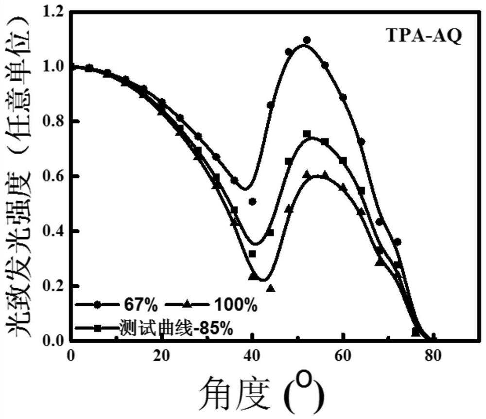
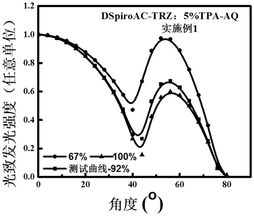
Embodiment 1

[0098] This embodiment provides a combined luminescent material, wherein:

[0099] Including 5wt% guest material, and 95wt% host material;

[0100] The host material is DSpiroAC-TRZ, which is thermally activated delayed fluorescence with horizontal orientation of high transition dipole moment, and the single-triplet exchange energy is 0.04 eV. The preparation method is shown in formula (1);

[0101] The guest material is TPA-AQ, and the preparation method is shown in formula (8).

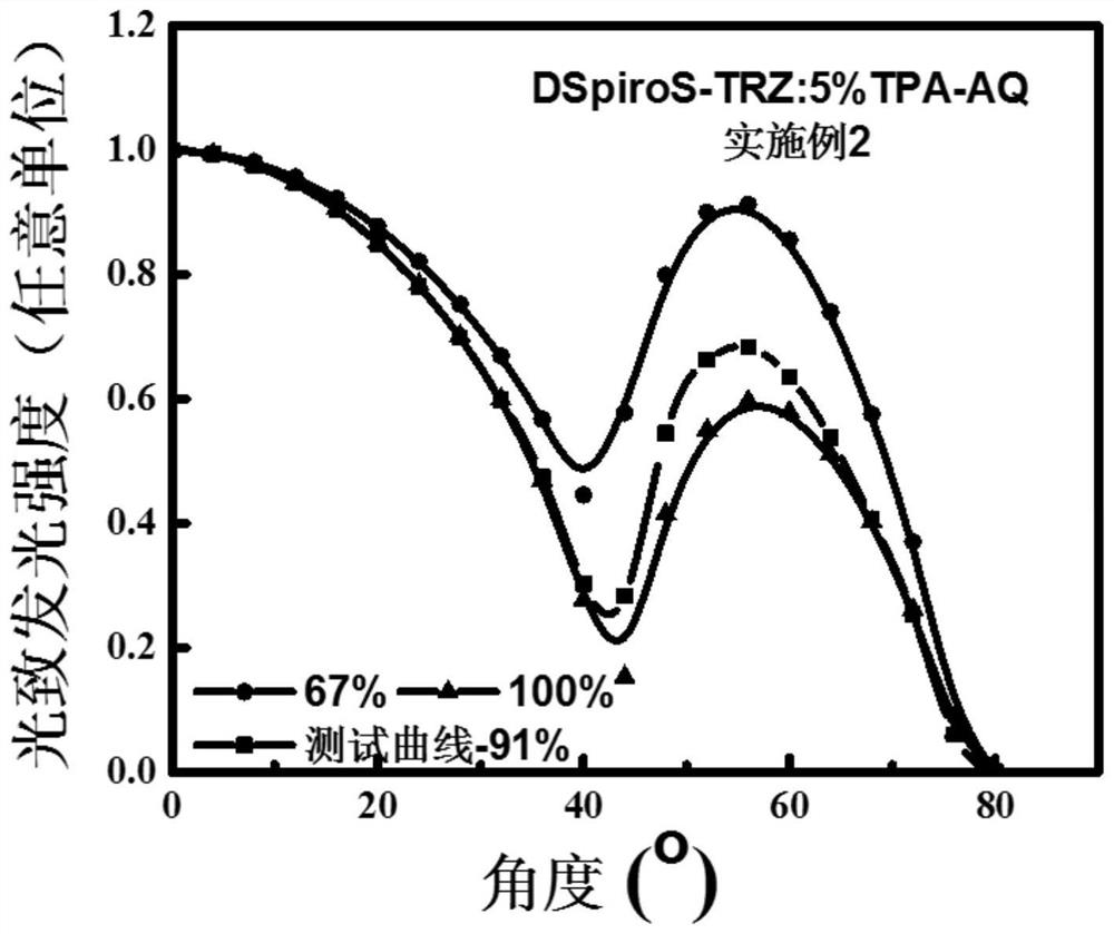
Embodiment 2

[0103] This embodiment provides a combined luminescent material, wherein:

[0104] Including 5wt% guest material, and 95wt% host material;

[0105] The host material is DSpiroS-TRZ, which is thermally activated delayed fluorescence with a high transition dipole moment horizontal orientation, and the single-triplet exchange energy is 0.05 eV. The preparation method is shown in formula (2);

[0106] The guest material is the same as that used in Example 1.

Embodiment 3

[0108] This embodiment provides a combined luminescent material, wherein:

[0109] Including 5wt% guest material, and 95wt% host material;

[0110] The main material is the same as in Example 1;

[0111] The guest material is DBXZ-2FDBPZ, and the preparation method is shown in formula (9).


PUM


Abstract

The invention discloses a combined luminescent material and application thereof, belonging to the technical field of luminescent materials. The combined luminescent material of the present invention includes: a host material and a guest material; the horizontal orientation degree of the transition dipole moment of the host material is >80%; and the guest material is at least one of a thermally activated delayed fluorescent material and a traditional fluorescent material. In the present invention, a host material with a horizontal orientation degree of transition dipole moment>80% is combined with a luminescent guest material, the host material can sensitize the guest material, thereby improving the horizontal orientation degree of the transition dipole moment of the guest material, and the material is used for luminescence After the diode, the light extraction efficiency and external quantum efficiency of the diode can be improved.

Description

technical field [0001] The invention belongs to the technical field of luminescent materials, and particularly relates to a combined luminescent material and its application. Background technique [0002] Organic light-emitting diodes (OLEDs) have the advantages of high color contrast, fast response speed, low power consumption, no blue light hazard, and flexible display. They have been applied in solid-state lighting and display fields, and have good application prospects. [0003] The existing organic light-emitting materials mainly include: In 1998, Professor Forrest of Princeton University developed phosphorescent materials containing heavy metal atoms, and in 2008, Professor Adachi of Kyushu University in Japan developed a thermal activation delay with a small single triplet energy gap. fluorescent material. All of these materials can effectively utilize triplet excitons to achieve light emission, and can theoretically achieve 100% internal quantum efficiency, which me...

Claims


Application Information

Patent Timeline
Patent Type & Authority Patents(China)
IPC IPC(8): C07D401/10C07D495/10C07C225/24C07C221/00C07D413/14C09K11/06C09K11/07H01L51/50H01L51/54
CPCC07D401/10C07D495/10C07C225/24C07C221/00C07D413/14C09K11/06C09K11/07C09K2211/1029C09K2211/1059C09K2211/1037C09K2211/1014C09K2211/1011C09K2211/1033C09K2211/1044H10K85/615H10K85/631H10K85/654H10K85/6572H10K85/657H10K50/121
Inventor 苏仕健李文琪刘坤坤李伟彭晓媚
Owner SOUTH CHINA UNIV OF TECH
Learn More