
Inclined shaft TBM tunneling system and tunneling method

A technology for inclined wells and propulsion cylinders, which is applied in wellbore lining, shaft equipment, earthwork drilling and production, etc. It can solve the problems of increased length of TBM in inclined wells, achieve the effect of reducing the total length and ensuring stability

Pending Publication Date: 2021-08-06
CHINA RAILWAY ENGINEERING EQUIPMENT GROUP CO LTD
View PDF6 Cites 6 Cited by
  • Summary
  • Abstract
  • Description
  • Claims
  • Application Information

AI Technical Summary

Problems solved by technology

[0005] The purpose of the present invention is to provide an inclined shaft TBM excavation system to solve the technical problem that the safety anti-slip device in the prior art will occupy the length of a trailer, resulting in an increase in the length of the whole machine of the inclined shaft TBM; the purpose of the present invention is also To provide an inclined shaft TBM excavation method

Method used


Image

  • Inclined shaft TBM tunneling system and tunneling method
  • Inclined shaft TBM tunneling system and tunneling method
  • Inclined shaft TBM tunneling system and tunneling method

Examples


Embodiment 1

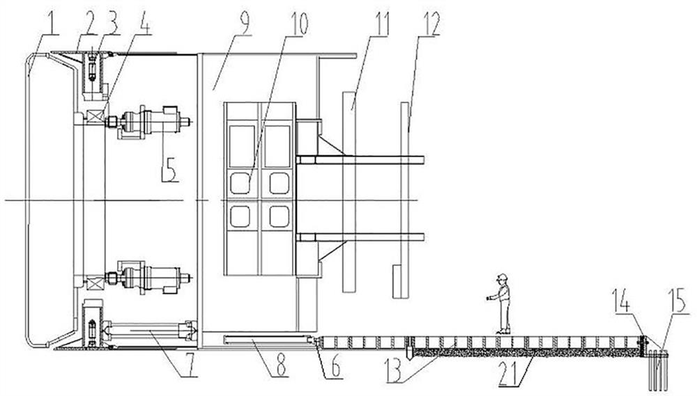
[0059] like figure 1 As shown, the inclined shaft TBM excavation system includes a front shield 2 and a support shield 9, a driving device is provided inside the front shield 2, and a cutterhead 1 is provided at the front end of the front shield 2. The driving device includes a driving motor 5 and a transmission mechanism 4, and the driving device When the motor 5 works, the cutter head 1 is driven to rotate through the transmission mechanism 4, so as to realize the cutting of the soil.

[0060] In this embodiment, the front end of the support shield 9 is inserted into the rear end of the front shield 2, and a propulsion cylinder 7 is provided between the support shield 9 and the front shield 2, so that the front shield 2 moves forward relative to the support shield 9 in the front-rear direction. move. Wherein, one end of the propulsion cylinder 7 is connected to the bottom of the support shield 9, and the other end of the propulsion cylinder 7 is connected to the bottom of t...

Embodiment 2

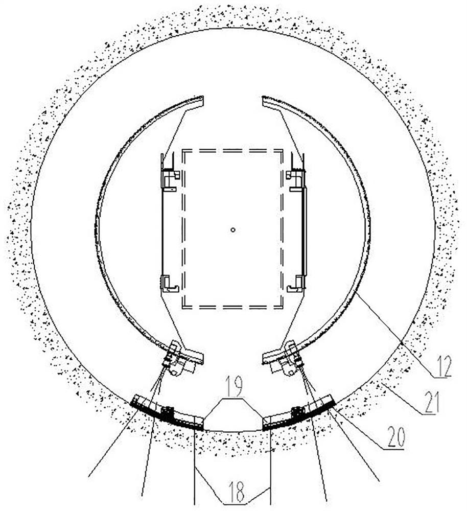
[0082] The difference between this embodiment and Embodiment 1 is that in Embodiment 1, an arch concrete layer 20 is provided between the arch 19 and the arch anchor 18 to improve the stability of the arch. In this embodiment, the arch concrete layer is not provided, and the stability of the arch is improved by increasing the diameter and quantity of the anchor rods of the arch.

Embodiment 3

[0084] The difference between this embodiment and Embodiment 1 is that in Embodiment 1, the support assembly 13 includes a plurality of arches 19 , and all the arches 19 of the support assembly 13 are arranged in abutment along the front-rear direction. In this embodiment, based on the fact that the support assembly includes a plurality of arches, all the arches of the support assembly are arranged at intervals along the front-rear direction, and the distance between two adjacent arches is equal to one excavation stroke of the inclined shaft TBM.


PUM

PropertyMeasurementUnit
Apertureaaaaaaaaaa
Depthaaaaaaaaaa

Abstract

The invention relates to an inclined shaft TBM tunneling system and tunneling method. The inclined shaft TBM tunneling system comprises an anterior shield, a supporting shield, a supporting shoe assembly, a supporting assembly and an axial anti-slip oil cylinder, wherein a driving device is arranged in the anterior shield, a cutterhead is arranged at the front end of the anterior shield, and the driving device is used for driving the cutterhead to rotate; the front end of the supporting shield is inserted into the rear end of the front shield or arranged at the rear end of the front shield in a sleeving mode, and a thrust oil cylinder is arranged between the supporting shield and the front shield so that the front shield can move forwards relative to the supporting shield in the front-back direction; the supporting shoe assembly is arranged in the supporting shield, and the supporting shoe assembly and the thrust oil cylinder work cooperatively so as to achieve step changing of the inclined shaft TBM; the supporting assembly is arranged behind the supporting shield, the supporting assembly comprises an arch frame and an arch frame anchor rod, the arch frame anchor rod is inserted into the tunnel wall of a tunnel, and the arch frame is installed on the arch frame anchor rod and is attached to the tunnel wall; and the axial anti-slip oil cylinder extends in the front-back direction of the tunnel and is arranged in the supporting shield, and an axial supporting shoe is arranged at the driving end of the axial anti-slip oil cylinder and used for being supported on the arch frame so as to prevent the inclined shaft TBM from slipping.

Description

technical field [0001] The invention relates to an inclined shaft TBM excavation system and an excavation method. Background technique [0002] Hard rock tunnel boring machine (TBM) is a special construction machine for tunnel boring. It has the functions of excavating and cutting soil, transporting sludge, and assembling tunnel lining. It has been widely used in subways, railways, highways, municipalities, hydropower, etc. tunnel Engineering. Conventional TBMs are suitable for flat tunnel construction with a slope of ±5%, while inclined shaft TBMs need to be equipped with safety anti-slip devices when driving upwards to avoid the problem of downward slipping of inclined shaft TBMs. [0003] The Chinese invention patent application with the application publication number CN112412478A discloses a tunnel construction system for an inclined shaft, including a starting device, an inclined shaft TBM, and a receiving device. There is a safety anti-slip device, which prevents the...

Claims


Application Information

Patent Timeline
IPC IPC(8): E21D9/087E21D9/06E21D11/18E21D20/00
CPCE21D9/0873E21D9/0621E21D11/18E21D20/003
Inventor 贺飞于庆增宁向可张喜冬毛晴松秦庆华鲁义强
Owner CHINA RAILWAY ENGINEERING EQUIPMENT GROUP CO LTD
Learn More