Underground light source well drilling system

A light source and drilling technology, which is applied to the automatic control system of drilling, drilling equipment, application of thermal energy drilling, etc., can solve the problems of downhole light sources such as complex downhole environment adaptability, and achieve the effects of compact structure, expanded application range, and increased output power

Active Publication Date: 2021-08-10
LASER FUSION RES CENT CHINA ACAD OF ENG PHYSICS
View PDF13 Cites 1 Cited by
  • Summary
  • Abstract
  • Description
  • Claims
  • Application Information

AI Technical Summary

Problems solved by technology

[0005] Aiming at the deficiencies of the existing technology, a downhole light source drilling system is proposed to solve the problems of downhole light source miniaturization and complex downhole environment adaptability, etc.

Method used


Image

  • Underground light source well drilling system
  • Underground light source well drilling system
  • Underground light source well drilling system

Examples


Embodiment 1

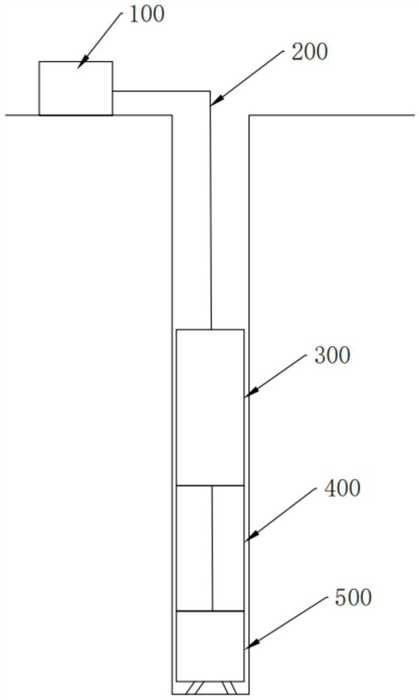
[0034] A downhole light source drilling system, such as figure 1 As shown, it includes an external power supply, a transmission cable 200, a downhole light source 300 arranged downhole for emitting laser beams to the downhole working face, a laser drill collar 400 and a laser drill bit 500 arranged in sequence along the laser beam emission direction, and the external power supply passes through The transmission cable 200 is connected with the downhole light source 300 , the laser drill collar 400 and the laser drill bit 500 .

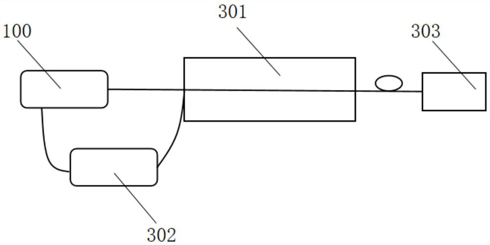
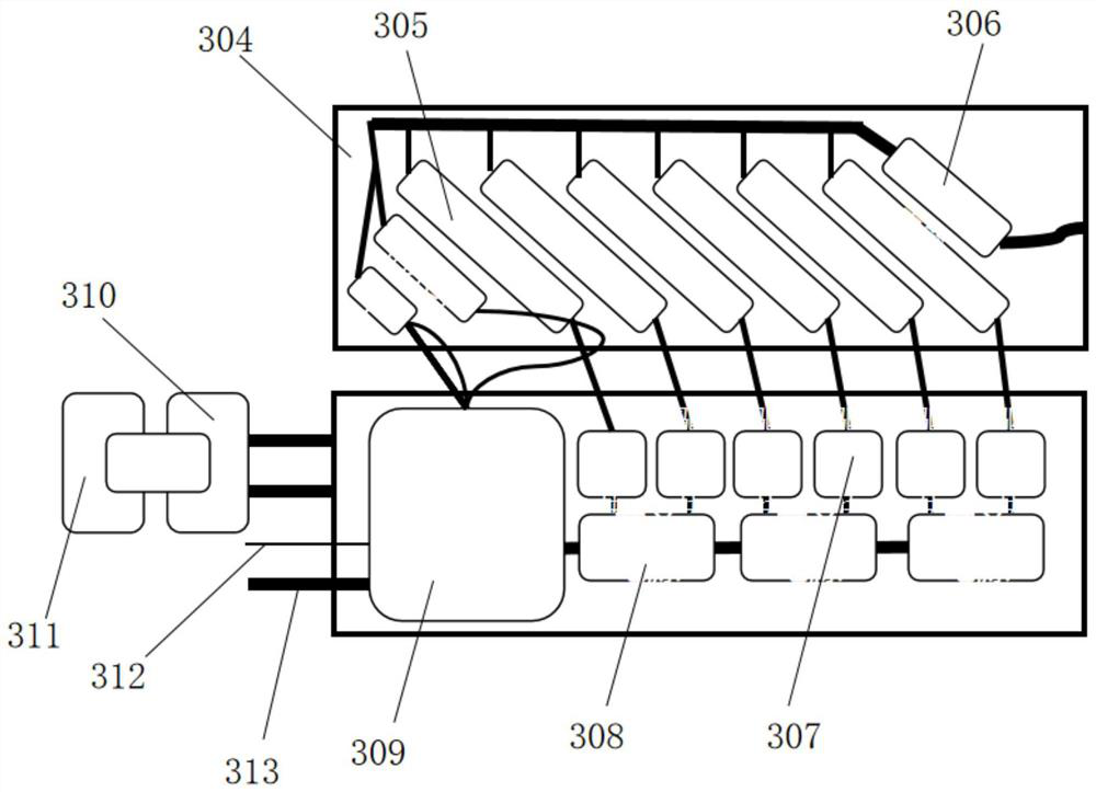
[0035] According to the miniaturization and high-efficiency requirements of the downhole light source, the downhole light source 300 adopts the method of optical fiber coupling and beam combining of semiconductor lasers, specifically, as figure 2 with image 3As shown, the downhole light source 300 includes an optical module, a driving module 307 and a temperature control module 302, wherein the optical module and the driving module 307 are packaged i...

Embodiment 2

[0044] Such as Figure 4 As shown, the same part of this embodiment and embodiment 1 will not be repeated, and the difference is:

[0045] In this embodiment, there are 3 groups of cascaded laser groups 314, and each group of cascaded laser groups 314 includes 5 sub-lasers 305 and 1 laser emitting indicating red light. The sub-lasers 305 located in the same group are combined through the first fiber combiner 306 to form the first combined laser beam, and the cascaded laser groups 314 are combined through the second fiber combiner 315 to form the second beam The second combined laser beam is used as an output beam.


PUM


Abstract

The invention discloses an underground light source well drilling system. The underground light source well drilling system comprises an external power source, a transmission cable, an underground light source arranged underground and used for emitting laser beams to an underground working face, a laser drill collar and a laser drill bit, wherein the laser drill collar and the laser drill bit are sequentially arranged in the emitting direction of the laser beams; and the external power source is connected with the underground light source, the laser drill collar and the laser drill bit through the transmission cable. The underground light source adopts semiconductor laser optical fiber coupling and beam combination, so that the requirements of underground light source drilling miniaturization and high efficiency are met; meanwhile, the problems of light source miniaturization and complex underground environment adaptability are solved, and laser drilling informatization and intelligentization are improved through measurement while drilling equipment and a well control system; and meanwhile, drilling matching is configured, auxiliary airflow and rock debris transportation are provided for laser drilling, and smooth proceeding of laser drilling is guaranteed.

Description

technical field [0001] The invention belongs to the technical field of laser rock breaking applications, and in particular relates to an underground light source drilling system. Background technique [0002] Abundant oil and gas resources in underground reserves are an important source of energy to support the progress and development of human society. With the long-term exploitation, the target layer of oil and gas exploration and development rapidly extends from the medium-shallow layer to the deep layer and ultra-deep layer. The problems faced by it, such as high hardness, poor drillability, and complex geological structure, make traditional drilling face great challenges. The bottleneck of drilling technology, seeking new technology research and development, achieving deeper depth, more complex working conditions, faster efficiency while reducing costs is the goal that the oil and gas industry has been pursuing. [0003] With the advancement and development of science ...

Claims


Application Information

Patent Timeline
Patent Type & Authority Applications(China)
IPC IPC(8): E21B7/15E21B21/16E21B47/002E21B44/00
CPCE21B7/15E21B21/16E21B44/00
Inventor 朱启华康民强邓颖粟敬钦朱灿林李剑彬强永发蒋学君郑建刚彭志涛郑奎兴郑万国
Owner LASER FUSION RES CENT CHINA ACAD OF ENG PHYSICS
Why Eureka
Try Eureka