
Electromagnetic ejection underground hydraulic pulsation generating device and using method thereof

A technology of electromagnetic ejection and generating device, which is applied to earth-moving drilling, wellbore/well components, and production fluids, etc. Small area, improved pore sweep rate and recovery factor, and the effect of expanding sweep range

Active Publication Date: 2021-08-10
CHINA UNIV OF PETROLEUM (EAST CHINA)
View PDF7 Cites 0 Cited by
  • Summary
  • Abstract
  • Description
  • Claims
  • Application Information

AI Technical Summary

Problems solved by technology

Installing high-pressure energy storage devices on the ground, on the one hand, will bring pressure to the well site space and increase the floor area; on the other hand, the safety risks of the high-pressure energy storage devices on the ground are high, and at the same time, the string strength requirements are high

Method used


Image

  • Electromagnetic ejection underground hydraulic pulsation generating device and using method thereof
  • Electromagnetic ejection underground hydraulic pulsation generating device and using method thereof
  • Electromagnetic ejection underground hydraulic pulsation generating device and using method thereof

Examples


Embodiment 1

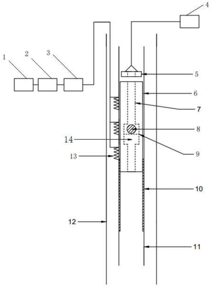
[0035] Such as Figure 1-4 As shown, this embodiment provides an electromagnetic catapult downhole hydraulic pulsation generating device, including a ground energy supply system, a lifting system, an electromagnet 5, an catapult system, an oil pipe 11, a plunger pump barrel 10 and an acceleration coil 13, wherein,

[0036] The ground is provided with a lifting system, the lifting system is connected with an electromagnet 5, the electromagnet 5 is arranged in the oil pipe 11, and the oil pipe 11 below the electromagnet 5 is provided with a plunger pump barrel 10, and the plunger pump barrel 10 is equipped with an ejector. system, the outside of the oil pipe 11 above the plunger pump barrel 10 is provided with an acceleration coil 13, and the acceleration coil 13 is connected to a ground energy supply system. The acceleration coil uses copper core PVC insulated wire, the wire core diameter is 2mm, the insulation thickness is 1mm, and the calculated outer diameter is 4mm.

[003...

Embodiment 2

[0056] An electromagnetic catapult downhole hydraulic pulsation generating device, the structure of which is as described in Embodiment 1, the difference is that a screen 9 is provided in the middle of the reaming cavity 14, and the movement range of the ball valve is narrowed by the screen to improve the sealing effect of the ball valve.

[0057] This embodiment is applied to oil layers with a well depth of 4700m, a reservoir pressure of 50MPa, and a fracture pressure of 90Mpa. The structural dimensions are designed as follows:

[0058] The length of the oil pipe is 30m, the outer diameter of the oil pipe is 88.9mm, the wall thickness is 6.45mm, and the inner diameter is 76mm;

[0059] The outer diameter of the electromagnet is 70mm, and the diameter of the through hole is 20mm;

[0060] The length of the ejection core is 15m, the outer diameter is 73mm, and the diameter of the cylindrical cavity is 20mm;

[0061] Reaming chamber length 40mm, diameter 30mm;

[0062] Ball va...

Embodiment 3

[0065] An electromagnetic ejection downhole hydraulic pulsation generating device, the structure is as described in Embodiment 1, the difference is that the acceleration coil 13 is arranged around the outside of the oil pipe 11, and the number of turns of the acceleration coil at the middle position is greater than the number of turns of the acceleration coil at both ends, so that the magnetic field As the gradient increases, the ejection force increases. The acceleration coil is provided with 3 sections to realize the multi-stage acceleration of the ejection system.


PUM


Abstract

The invention relates to an electromagnetic ejection underground hydraulic pulsation generating device and a using method thereof, and belongs to the technical field of oil and gas exploitation equipment. The device comprises a ground energy supply system, a lifting system, an electromagnet, an ejection system, an oil pipe, a plunger pump cylinder and an acceleration coil, wherein the lifting system is arranged on the ground and connected with the electromagnet; the electromagnet is arranged in the oil pipe; the plunger pump cylinder is arranged in the position, below the electromagnet, of the oil pipe; the ejection system is sleeved with the plunger pump cylinder; and the acceleration coil is arranged on the outer side of the oil pipe above the plunger pump cylinder and connected with the ground energy supply system. The device is small in occupied area, simple in structure, convenient and safe to use, large in electromagnetic ejection energy, easy to control and capable of achieving intelligent management and control, the water drive efficiency is improved under the hydraulic pulsation effect, the sweep range is expanded, and the pore sweep rate and recovery rate are improved.

Description

technical field [0001] The invention relates to an electromagnetic catapult downhole hydraulic pulsation generating device and a method for using the same, belonging to the technical field of oil and gas exploitation equipment. Background technique [0002] With the development of oil and gas, many oilfields have entered the stage of high water cut in the middle and late stage of development, and a large amount of remaining oil is trapped underground due to the strong heterogeneity of the reservoir, which has become an important material basis for the stable production of old oilfields. For medium-high permeability reservoirs, chemical flooding is generally used in the high water-cut stage, and chemical agents are added to the injected water to improve the sweep coefficient and oil washing efficiency of the injected fluid. In the process of chemical flooding, many problems have arisen. For different oil fields and different blocks, different chemical agents need to be config...

Claims


Application Information

Patent Timeline
Patent Type & Authority Applications(China)
IPC IPC(8): E21B43/20E21B43/25
CPCE21B43/20E21B43/25
Inventor 吴飞鹏姜智浩刘静赵志强杨维
Owner CHINA UNIV OF PETROLEUM (EAST CHINA)
Learn More