
Coal-fired boiler flue gas decarburization device

A technology for coal-fired boilers and decarbonization, which is applied to combined devices, gas treatment, combustion methods, etc., can solve problems such as single-function reaction conversion and collection, and achieve the effect of easy operation and installation, and improved decarbonization effect.

Active Publication Date: 2021-08-17
新疆海天祥瑞环保工程有限公司
View PDF13 Cites 0 Cited by
  • Summary
  • Abstract
  • Description
  • Claims
  • Application Information

AI Technical Summary

Problems solved by technology

[0006] The purpose of the present invention is to: reduce the production of carbon monoxide from the furnace body by setting a preheating calcination system, and then filter the carbon dust in the flue gas by setting a convective cyclone decarburization device, convert a small amount of carbon monoxide into carbon dioxide, and convert a large amount of carbon dioxide Carry out reaction conversion collection to solve the problem of reaction conversion collection of carbon monoxide or carbon dioxide in existing devices or systems with relatively single functions. In order to solve the proposed problem, a coal-fired boiler flue gas decarbonization device is proposed

Method used


Image

  • Coal-fired boiler flue gas decarburization device
  • Coal-fired boiler flue gas decarburization device
  • Coal-fired boiler flue gas decarburization device

Examples


Embodiment 1

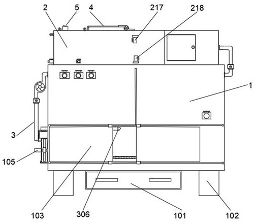
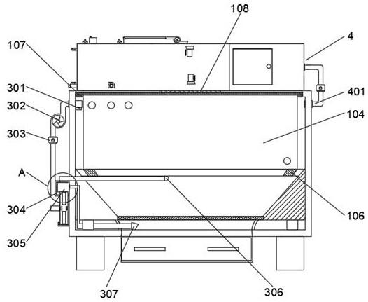
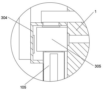
[0035] A coal-fired boiler flue gas decarburization device, including a furnace body 1, a first dust collection drawer 101, a support column 102, a split sealed door 103, a heating water tank 104, a blower 105, a frame-shaped support 106, and a convective cyclone decarburization device 2 and the preheating calcining system 3, the heating water tank 104 is fixedly installed in the furnace body 1, and a coal pallet is fixed between the heating water tank 104 and the bottom plate of the furnace body 1, and the coal pallet is provided with ash drop holes, and the coal is placed on the coal On the supporting plate, the support column 102 is fixedly arranged at the four corners of the bottom end of the furnace body 1, the air blower 105 is fixedly arranged on one side of the furnace body 1, the first dust collecting drawer 101 is fixedly arranged at the bottom end of the furnace body 1, and the second A dust collection drawer 101 is used to receive coal ashes, and the sealed door 103...

Embodiment 2

[0051] In Example 1, the carbon is detached by preheating the calcination system 3 and the convective rotary decarburization device 2, wherein the first convective carbon adsorption part 210, the second convective carbon adsorption part 211 and the third convective carbon adsorption part 2 in the convective rotary decarburization device 2 The carbon adsorption part 212 needs to continuously adsorb the carbon dust in the flue gas. When the carbon dust accumulates in the first convective carbon adsorption part 210, the second convective carbon adsorption part 211 and the third convective carbon adsorption part 212, it is generally fixed The method is usually fixed by bolts, the function is too single, and this method is not convenient enough to operate, which affects work efficiency;

[0052] The adsorption chamber 204 is also provided with a support block 213 and a locking assembly 214. The support block 213 is fixed at the bottom of the decarburization chamber 201, and the uppe...


PUM


Abstract

The invention discloses a coal-fired boiler flue gas decarburization device, and relates to the technical field of coal-fired boiler decarburization. The coal-fired boiler flue gas decarburization device comprises a convection rotation decarburization device and a preheating calcination system; and the convection rotation decarburization device comprises a decarburization bin fixedly arranged at the top end of a boiler body and four partition plates, wherein the decarburization bin is in clearance fit with the four partition plates to form a filter cavity, an adsorption cavity, a first reaction cavity, a second reaction cavity and a pressure discharge cavity. Carbon in the boiler is treated by arranging the preheating calcining system and the convection rotating decarburization device, the carbon is sufficiently combusted firstly, and then a small amount of carbon monoxide in the carbon is re-calcined, so that the content of the carbon monoxide in the boiler body is reduced; and then when the air pressure of the boiler body is too high, smoke enters the convection rotating decarburization device, and after carbon dust in flue gas is filtered and adsorbed, carbon monoxide reacts and is converted into carbon dioxide, and then the carbon dioxide reacts and is stored, so that carbon is separated in a multi-layer manner.

Description

technical field [0001] The invention relates to the technical field of decarbonization of coal-fired boilers, in particular to a coal-fired boiler flue gas decarbonization device. Background technique [0002] In recent years, the greenhouse effect has gradually become one of the most serious problems faced by human beings. Carbon dioxide is one of the most important factors causing the greenhouse effect. The boiler exhaust gas used in daily life contains a large amount of carbon dust, carbon dioxide, sulfide and other Impurities, among which the existing boilers are generally directly discharged into the atmosphere, and after being discharged from the chimney, it will cause great pollution to the environment; [0003] The application number is CN201821976020.2, a boiler tail gas decarburization device, which effectively solves the problem of high energy consumption in the past where flue gas dispersion needs to be pressurized through the gas dispersion form based on the Ven...

Claims


Application Information

Patent Timeline
Patent Type & Authority Applications(China)
IPC IPC(8): B01D53/62B01D53/75B01D53/81B01D53/78B01D50/00F23L15/00F23J15/00F23J15/02
CPCB01D53/62B01D53/75B01D53/81B01D53/78B01D50/00F23L15/00F23J15/006F23J15/025B01D2251/602B01D2251/404B01D2251/604B01D2257/502B01D2257/504B01D2258/0283F23J2215/40F23J2215/50Y02A50/20Y02E20/34Y02E20/32Y02C20/40
Inventor 姜顺民叶晓莲
Owner 新疆海天祥瑞环保工程有限公司
Learn More